
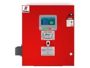
Firetrol FTA1100J Diesel Engine Fire Pump Controller is intended for starting and monitoring fire pump diesel engines. They are suitable for use with both mechanical and electronic-type engines. The controller is available for 12 or 24-volt negative ground systems, using lead acid or Nickel-Cadmium batteries. The controller monitors, displays, and records fire pump system information.
Approvals: Firetrol fire pump controllers are listed by Underwriters’ Laboratories, Inc., in accordance with UL218, Standard for Fire Pump Controllers, CSA, Standard for Industrial Control Equipment (cUL), and approved by Factory Mutual. They are built to meet or exceed the requirements of the approving authorities as well as NEMA and the latest editions of NFPA 20, Installation of Centrifugal Fire Pumps, and NFPA 70, National Electrical Code.
Features Overview :
- 7? Capacitive Color Touchscreen
- AC Line & Battery Circuit Breakers
- Weekly Test Timer
- Manual Crank Buttons
- Digital Pressure Display
Features
The following are included as standard with each controller:
- NEMA Type 2 (IP22) Enclosure with Bottom Entry Gland Plate, Lifting Lugs, and Locking Door Handle
- AC Line & Battery circuit breakers
- Two independent battery chargers, 10A continuous charge – 500mA Trickle Charge
- 7.0” LCD capacitive type color touch screen (HMI technology) software upgradeable operator interface powered by an embedded microcomputer with software PLC logic.
- Push-buttons for Crank from Battery #1, Crank from Battery #2, Stop and Run Test
- 500 PSI Pressure Transducer (calibrated for 300 PSI (20.7 Bar) and Test Solenoid for freshwater applications, externally mounted with a protective cover
- Audible alarm buzzer embedded in the MarkIII+
- Pressure and Event Recording with Date Stamp to System Memory Accessible VIA The User Interface and Downloadable to a USB Flash Drive
- Visual Indication for Engine Run
- Main Switch Position
- Periodic Test
- Cranking Cycle
- AC Power Available
- Pump Room Temperature
- Visual Alarm Indication for: Pump Room Trouble
- Pump On Demand
- AC Power Failure
- Charger 1-2 Failure
- Battery 1-2 Weak
- Battery 1-2 Overvoltage
- Loss of Continuity on Starter 1-2
- High Fuel Level
- Fuel Tank Leak
- PLD Low Suction Pressure
- High Raw Water Temp.
- Low Pump Room Temp.
- High Pump Room Temp.
- ECM Warning
- Weekly Test Cut-In Pressure Not Reached
- Check Weekly Test Solenoid
- Pressure Transducer Fault
- Invalid Cut-In Pressure
- Service Required
- MarkIII+ Diesel Engine Fire Pump Controller
Applications
They are suitable for use with :
- Both Mechanical
- Electronic type Engines
Specifications
Main Fire Pump Controller
The main fire pump controller shall be a factory-assembled, wired and tested unit. The controller shall be of the combined manual and automatic type designed for diesel engine operation of the fire pump. The controller shall be rated for an Ambient Temperature Operating Range of 39ºF (4ºC) to 104ºF (40ºC).
Standards, Listings & Approvals
The controller shall conform to all the requirements of the latest editions of:
- NFPA 20
- UL (UL218 and CSA 2 No. 14)
- FM Global (Class 1321/1323)
- The city of New York for fire pump service
Enclosure
- The controller components shall be housed in a NEMA Type 2 (IEC IP22) drip- proof, wall-mounted enclosure with a bottom entry gland
Operator Interface (HMI)
7.0” LCD capacitive type color touch screen (HMI technology) operator interface powered by an embedded microcomputer with software PLC logic. Included shall be keypad type push-buttons for Crank from Battery #1, Crank from Battery #2, Stop and run test. The screen shall include menus for: Home · Alarms · Configuration · History · Ser- vice · Manuals · Language. The HMI shall graphically display the following: AC Power Present · Charger #1 & #2 Charging Mode · Battery #1 & #2 Voltage and Amperage · System Pressure
- Cut In and Cut Out Pressure Settings Starter #1 and #2 Cranking or Resting · Engine Running · Starting Cause · Fuel Valve Energized · Timers Operation · H-O-A Switch Position · Actuation Mode · Controller Type · Shutdown Mode · Time & Date
- Pump Room Temperature System Pressure
- System pressure shall be capable of being displayed as: PSI, kPa, Bar, Feet of Head or Meters of
The HMI shall allow programming and display of: Cut In & Cut Out Pressure Set- tings · Minimum Run Timer · Sequential Start Timer · Periodic Test Timer
The HMI allows the user to select the language of the system and download the manual or view the manual on screen.
State and Alarm Visual Indication
The digital display shall visually indicate and color code by criticalness the fol lowing:
- AC Fail
- DC Fail
- Battery 1/2 Fail
- Charger 1/2 Fail
- Engine Trouble
- Pump Room Trouble
- Controller Trouble
- Service Required
- Battery 1/2 Weak
- Loss of Con- tinuity with Starting Contactor 1/2
- Weekly Test Start Pressure Not Reached
- Weekly Test Check Solenoid Valve
- Faulty Pressure Transducer
- Low Raw Water Flow
- Engine Fail When Running
- Engine Fail To Start
- Engine Overspeed
- Low Ambient Temp.
- Pump On Demand
- Invalid Cut-In
- Overpressure
- Underpressure
- Battery 1/2 Overvoltage
- Water Reservoir Low
- Fuel Tank Leak
- Low Fuel Level
- High Fuel Level
- Engine ECM In Alternate Position
- Engine Fuel Injection Malfunction
- Engine High Temperature
- Engine Low Temperature
- Engine ECM Warning
- Engine ECM Fault
- Engine Low Oil Pressure
- High Raw Water Temperature
- Low Suction Pressure
- Engine Run
- Main Switch In Auto
- Pump Room Temperature
- Periodic Test
- Main Switch in Hand
- Cranking Cycle
- Main Switch In Off
- AC Power Available
Pressure and Event Recording
The system shall be capable of logging pressure data and operational events with time/date stamp. The system shall display operational events for the life- time of the controller and display the pressure data in text or graphical form.
The controller shall log the Date/Time of the first start-up and the controller total power on time from that date. The controller shall log first and last statistics for:
- First Setup
- On Time
- Engine On Time
- Engine Start Count
- Engine Last Start Time
- Min/Max/Average System Pressure
- Min/Max/Average Pump Room Temp
- Jockey Pump On Time
- Jockey Pump Start Count
- Jockey Pump Last Start Time
USB Host Controller
A USB port capable of accepting a USB Flash Memory Disk shall be provided for downloading pressure and event logs.
Serial Communications
The controller shall feature Modbus with TCP/IP frame format and a shielded fe- male RJ45 connector.
Pressure Sensing / Wet Parts
The controller shall be supplied with a solid state pressure transducer with a range of 0-500 psi calibrated for 0-300 psi (0-20.7 bar) and a run test solenoid valve. The wet parts shall be externally mounted and include a protective cover. The pressure sensing line connection to the transducer shall be 1/2-inch FNPT. Provisions for a redundant pressure transducer shall be provided.
Seismic Certification
The controller shall be certified to meet or exceed the requirements of the 2018 International Building Code, the 2019 California Building Code and OSHPD Special Seismic Certification Preapproval – OSP. The controller test criteria shall be per ICC-ES AC156 and the Seismic Parameters per ASCE 7-10 Chapter 13.
Controller Operation
On a call to start, the controller will crank from battery 1 for 15 seconds then rest for 15 seconds before cranking on battery 2. This cranking cycle shall repeat 3 times. If a running signal is not received from the engine, the controller will alarm “Fail To Start”.
The controller shall have the capability to schedule service reminders. The con- troller also provides for inputting of pump flow test data, generating and dis- playing the pump curve and permanently storing this data in memory.
Provisions shall be available for connection of external devices for Manual Re- mote Start, Automatic Remote Start and Deluge Valve Start.
DPDT dry contacts rated 8A – 250VAC shall be provided for remote indication of:
- Engine Run
- Main Switch in Hand or Off
- Controller Trouble (common)
- Engine Trouble (common)
- Pump Room Trouble (common)
- An audible alarm device shall be provided on the controller.
For More Information and Price: Firetrol FTA1100J Diesel Engine Fire Pump Controller
Read More Articles:
- Adalet Hazlo Products and Genlo Product
- Eurofyre fire detection and safety
- Flow Meter Pompa Hydrant Gerand untuk Sistem Pemadam Kebakaran
- Firetrol FTA200A Alarm Panel & Fire Pump Controllers
- Viking Fire Protection System