
Overview
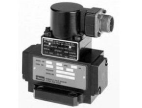
The direct operated control valve Parker D1FP Hydraulic Proportional of the nominal size NG06 (CETOP 03) shows extremly high dynamics combined with maximum flow. It is the preferred choice for highest accuracy in positioning of hydraulic axis and controlling of pressure and velocity.
Driven by the patented VCD® actuator the D1FP reaches the frequency response of real servo valves. Compared with solenoid driven valves the D1FP can also be used in applications with pressure drops up to 350 bar across the valve. Because of the high flow capability the D1FP can be a substitute for NG10 valves in some cases. At power-down the spool moves in a defined position. All common input signals are available.
Parker D1FP Hydraulic Proportional Features
- Real servo valve dynamics (-3 dB / 350 Hz at ±5 % input signal)
- No flow limit up to 350 bar pressure drop through the valve
- Max. tank pressure 350 bar (with external drain port y)
- High flow
- Defined spool positioning at power-down – optional P-A/B-T or P-B/A-T or center position (for overlapped spools)
- Onboard electronics
Specification
| Max. operating pressure | [bar] | Ports P, A, B 350, port T 35 for internal drain, 350 for external drain, port Y 35 2) | |
| Fluid | Hydraulic oil according to DIN 51524 … 535, other on request | ||
| Fluid temperature | [°C] | -20…+60 (NBR: -25…+60) | |
| Viscosity | permitted | [cSt]/mm²/s] | 20…400 |
| recommended | [cSt]/mm²/s] | 30…80 | |
| Filtration | ISO 4406; 18/16/13 | ||
| Nominal flow at ?p=35 bar per control edge3) | [l/min] | 3 / 6 / 12 / 16 / 25 / 40 | |
| Flow maximum | [l/min] | p=350 bar over two control edges) | |
| Leakage at 100 bar | [ml/min] | 90 (at ?p=350 bar over two control edges) | |
| Opening point | [%] | <400 (zerolap spool); <50 (overlap spool) | |
| Static / Dynamic | |||
| Step response at 100 % step 4) | [ms] | <3.5 | |
| Frequency response (±5 % signal) 4) | [Hz] | 350 (amplitude ratio -3 dB), 350 (phase lag -90°) | |
| Hysteresis | [%] | <0.05 | |
| Sensitivity | [%] | <0.03 | |
| Temperature drift | [%/K] | <0.025 | |
| Electrical characteristics | |||
| Duty ratio | [%] | 100 | |
| Protection class | IP65 in accordance with EN 60529 (with correctly mounted plug-in connector) | ||
| Supply voltage/ripple | [V] | DC 22 … 30, electric shut-off at < 19, ripple < 5 % eff., surge free | |
| Current consumption max. | [A] | 03.05 | |
| Pre-fusing | [A] | 4.0 medium lag | |
| Input signal | |||
| Code B | Voltage | [V] | 10…0…-10, ripple <0.01 % eff., surge free, 0…+10 V P->A |
| Impedance | [kOhm] | 100 | |
| Code E | Current | [mA] | 20…0…-20, ripple <0.01 % eff., surge free, 0…+20 mA P->A |
| Impedance | [Ohm] | <250 | |
| Code S | Current | [mA] | 4…12…20, ripple <0.01 % eff., surge free, 12…20 mA P->A |
| <3.6 mA = disable, >3.8 mA = according to NAMUR NE43 | |||
| Impedance | [Ohm] | <250 | |
| Differential input max. | Code 0 | [V] | 30 for terminal D and E against PE (terminal G) |
| Code 5 | [V] | 30 for terminal 4 and 5 against PE (terminal | |
| Code 7 | [V] | 30 for terminal D and E against PE (terminal G) | |
| Enable signal (only code 5/7) | [V] | 5…30, Ri = > 8 kOhm | |
| Diagnostic signal | [V] | +10…0…-10 / +12.5 error detection, rated max. 5 mA | |
| EMC | EN 61000-6-2, EN 61000-6-4 | ||
| Electrical connection | Code 0/7 | 6 + PE acc. EN 175201-804 | |
| Code 5 | 11 + PE acc. EN 175201-804 | ||
| Wiring min. | Code 0/7 | [mm²] | 7×1.0 (AWG 16) overall braid shield |
| Code 5 | [mm²] | 8×1.0 (AWG 16) overall braid shield | |
| Wiring length max. | [m] | 50 | |
- If valves with onboard electronics are used in safety-related parts of control systems, in case the safety function is requested, the valve electronics voltage supply is to be switched off by a suitable switching element with sufficient reliability
- For applications with pT>35 bar (max. 350 bar) the Y-port has to be connected and the plug in the Y-port has to be removed.
- Flow rate for different p per control edge: Qx = QNom. pxp Nom.
- Measured with load (100 bar pressure drop/two control edges).
Download Datasheet: Parker D1FP Direct Operated Proportional DC Valve
other Article:
- Parker 4 Way 3 Position Spoo
- Hydac Hydraulic Axial Piston Pump PPV Series
- Kofloc Proportional Solenoid Valve Model 3000
- Flow Control Valve Kofloc
- Haskel Air Driven Liquid Pumps