
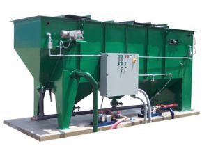
SkimOil API Oil Water Separator are passive, physical separation systems designed for the removal of oils, fuels, hydraulic fluids, LNAPL, and DNAPL products from water. Skimoil’s designed performance can be described by a combination of Stoke’s Law and current coalescing plate theory, wherein, the oil droplet rise rate and other parameters dictate the surface area required for gravity & coalescent separation.
Procedure for Separation for SkimOil API Oil Water Separator
After entering the separator, the water/oil mixture is dispersed horizontally via a turbulence and energy diffusing mechanism. The mixture enters the Flow-Thru media, where the oils impinge on the media surface and laminar and sinusoidal flow are formed. Larger droplets form as oils build up and ascend through the pack’s corrugations until they reach the top, where they separate and rise to the water’s surface. Solids come into contact with the media at the same time and slide down the corrugations, landing in the v-hopper beneath the Flow-Thru media.
To give engineers, system integrators, and end users comfort and flexibility in their system integration choices, API Oil/Water Separators are built with a multitude of functions and options. Modifications and customization are possible.
The following products were eliminated: vegetable-based oils, crude, air compressor lube, hydraulic fluids, immiscible machining oils, motor oils, fuels (vehicle/jet), fuel oils, bunker c, DNAPLs, LNAPLs, and several hydrocarbon-based derivatives (BTEX, etc.). The oil/fuel specific gravity, the required droplet size reduction, and other waste stream data are used to determine the model’s size.
Models and Flow Rates
| Model | Flow Rate (GPM) |
| API-15 | 15 |
| API-25 | 25 |
| API-50 | 50 |
| API-100 | 100 |
| API-150 | 150 |
| API-200 | 200 |
| API-250 | 250 |
| API-300 | 300 |
| API-400 | 400 |
| API-500 | 500 |
| Flow rates are nominal. The sizing of the system is based on application parameters. Contact Skimoil for the sizing of your application. | |
Features
- Integral oil reservoir
- Forkliftable skid, lifting lugs
- Flat bottom
- Sectional cover w/zinc hardware
- Carbon or Stainless steel construction
- Adjustable water weir
- Expandable effluent chamber
- Epoxy internal/external coatings
- 150 mg/L performance
PERFORMANCE
Oil/fuel removal 100 mg/L or less of oil droplets 150 micron and larger of non-emulsified, free and dispersed oils
Solids (TSS) 40 -100 mg/L
Influent concentration basis:
Oils 1250 mg/L or less influent loading
TSS 500 mg/L or less influent loading
While the API421 guide typically provides for an effluent discharge performance of 100 mg/L, 150 micron oil droplets it is possible with a properly designed API to provide performance down to 50 mg/L but not less. These performance figures are typically independent of the influent concentrations and are calculated as if in an ideal environment, which is not accurate to real-world experience. Actual performance is highly dependent on the type of waste entering the separator and the conditions within the separator.
Oil Water Separator Theory
- Coalescing Oil Water Separators: Coalescing Oil Water Separators are passive, physical separation systems designed for removal of oils, fuels, hydraulic fluids, LNAPL and DNAPL products from water. SkimOil designed performance can be described by a combination of Stokes Law and current coalescing plate theory, wherein, the oil droplet rise rate and other parameters dictate the surface area required for gravity & coalescent separation.
- Separation Process: The water/oil mixture enters the separator and is spread out horizontally, distributed through an energy and turbulence diffusing device. The mixture enters the Flow-Thru media where laminar and sinusoidal flow is established and the oils impinge on the media surface. As oils accumulate they coalesce into larger droplets, rising upward through the pack corrugations until they reach the top of the pack, where they detach and rise to the water’s surface. At the same time solids encounter the media and slide down the corrugations, falling into the v-hopper under the Flow-Thru media.
- Stokes Law: This equation relates the terminal settling or rise velocity of a smooth, rigid sphere in a viscous fluid of known density and viscosity to the diameter of the sphere when subjected to a known force field (gravity). The equation is:
V = (2gr²)(d1-d2)/9µ
where
V = velocity of rise (cm sec-¹),
g = acceleration of gravity (cm sec-²),
r = “equivalent” radius of particle (cm),
dl = density of particle (g cm -³),
d2 = density of medium (g cm-³), and
µ = viscosity of medium (dyne sec cm-²).
- Coalescence: Gravity separation utilizes the difference in specific gravity between the oil and water. Oil separates from a fluid at a rate explained by Stokes Law. The formula predicts how fast an oil droplet will rise or settle through water based on the density and size of the oil droplet size and the distance the object must travel. Our separators are built to exploit both variables of Stokes Law.
- With the use of our Flow-Thru media oil only need rise a short distance before encountering the oleophilic, coalescing media plates inside the separation chamber as opposed to rising a great distance in gravity separation. Upon impinging on the plates the oils coalesce (gather) into larger droplets until the droplet buoyancy is sufficient to pull away from the media and rise to the water’s surface. The design will meet particular design criteria as indicated below:
- The hydraulic distribution of the influent flow must assure full usage of the cross-sectional area of the media to fully utilize the plate pack’s surface area.
o Flow control and direction must be determined to prevent hydraulic short circuiting around, under or over the media pack.
o A laminar flow condition must be maintained (Reynolds “Re” number less than 500) in order to assist droplets to rise. Per the American Petroleum Institute’s (API) Publication 421 of February 1990.
o Horizontal flow through velocities in the separator must not exceed 3 feet per minute or 15 times the rate of rise of the droplets whichever is smaller.
o The media containment chamber design, plate design/angle and spacing sufficient to facilitate removal of accumulating solids. Plates are to be smooth surfaced and angled at 60 deg. - Flow-Thru Coalescing Media Design
SkimOil’s Flow-Thru coalescing media provides a laminar flow path that creates a quiescent zone to facilitate the impact with and attachment of oils to the media surface by reducing waste stream turbulence and velocity. This control of the waste stream creates a more ideal environment for oil removal. By virtue of our Flow-Thru media design, solids will also collide with the media and settle to the separator bottom to some degree. Due to oil typically being lighter than water, they (oil) will rise up the coalescing plate. As the oil droplets rise up the plate they will coalesce or come together with other droplets, creating progressively larger droplets. Once the droplet size is sufficient or the droplet reaches the top of the media plate the droplet pulls away from the plate and rises to the water surface. To some degree, the solids replicate this process in reverse (settling). - Gravity Separation vs. Coalescing Plates
Two types of oil water separator exist today in varying types of design, but all are dependent on these two types of design.
The first and oldest type is gravity or conventional separation, simple separation via gravity (density differential between two immiscible liquids leads to one of them rising above the other). This design, when designed properly (or even improperly) provides a certain tank length, width and depth that provides a wide, quiet spot in the pipeline to give oils time to rise. This design (also known as an API separator) generally provides a discharge oil concentration of 100 ppm based on a 150 micron droplet size. The API type design relies on a large water volume. This correlates to a tank size that can be 5 times the size of an equally sized coalescing separator. - The coalescing design is known by many names i.e. parallel plate, corrugated plate, slant rib coalescer so on and so forth. However, the concept, operation and design are generally the same. The coalescing concept is based on having a large surface area in contact with the waste stream (coalescing plates). The more surface area provided, the more enhanced the separation process will typically be. By using the coalescing media, the size of the tank is reduced and a higher performance is attained than by gravity separation. SkimOil Flow-Thru coalescing design provides a discharge oil concentration of 10 PPM or less with an oil droplet size of 30 or as small as a 20 micron oil droplet.
APPLICATIONS: OWS
- Groundwater Remediation
Contaminated ground water treatment for removal of gasoline, diesel, JP, jet fuels,
LNAPL, DNAPL, motor oils, kerosene, fuel oils and more. - Refineries
Removal of crudes, gasoline, diesel fuel, motor oils, transmission fluids,
hydraulic fluids, jet fuels, aircraft fuels from refining processes. - Vehicle Wash Racks
Removal of gasoline, diesel fuel, motor oils, transmission fluids, hydraulic fluids, jet fuels, aircraft fuels and lubricants when washing jets, cars, trucks, heavy equipment, railroad locomotives and equipment. - Military Wash Racks
Field equipment, jet wash, tracked equipment wash uses for typical fuels and oils removal. Complete treatment systems are offered. (Also see VEW systems) - Industrial Process Water
Hydraulic fluids, machining coolant/cutting fluid tramp oil removal, compressor condensate, machined parts rinse water. - Steel Mills
Rolling mill hydraulic oil/water extraction, compressor condensate, stormwater runoff, drain water. - Stormwater Treatment
Parking lot runoff, railroad re-fueling depot runoff, gas station runoff, bridge runoff. - Shipping Ballast & bilge water treatment.
Off-loading of water to shore based treatment system, bunker & diesel fuels removal. - Tank Farms
Fuel, oil storage tank farms for removal of water from tank bottoms. Stationary and mobile systems are offered. - Petro-Chemical
Refineries, chemical compounding companies, hydrocarbon based chemical bases such as cumene and other materials. - Power Generation
Generator lube oils, hydraulic oils, fuels. Stationary & mobile systems offered. - Heat Treating
Heat treating facility oily wash solution can be continuously treated.
Source: www.skimoil.com
Read more article:
- Oil Skimmers Model 5H Brill Horizontal Tube
- Oil Skimmers Model 6V Brill Vertical Tube
- Oil Skimmers Model 7V Brill High Capacity 1-Inch Tube
- SkimOil Mini-Brute Oily Water Separators
- SkimOil Brute Marine Oily Water Separator