
Philmac Servo Tank Filling Valve
These WaterMark approved* valves are rated to 2000 kPa (290 psi) static shut-off. This means the valve can be installed for mains water supply and industrial applications. * Also known as potable water. The valves are approved to the AS/NZS 4020 standard which means they can be confidently used in applications that are required for drinking water. * Also known as potable water.
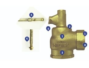
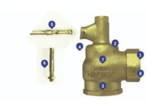
The secondary (or servo) action allows these valves to have a much larger seat than a similarly sized valve. This allows for a greater flow and makes them ideally suited to applications such as filling fire water tanks. The valve has been designed for easy disassembly by removing the pivot pin and body outlet to allow access to all internal parts.
By using a robust machined cam that interlocks with the secondary plunger it ensures reliable opening and closing of the valve time after time. Once the 10” copper floats are wound into the lever a nut and split pin are fitted to ensure it does not come loose. The body is manufactured from quality dezincification bronze. This ensures it is resistant to the loss of zinc which would otherwise cause leakage and premature failure.
The range is comprehensive and includes sizes from 1-½” to 3” BSP to suit a range of tank sizes. The outlet has a female thread which allows a threaded fitting or pipe to be attached and direct the water as required. ** Connections to mains water must comply with the relevant air gap regulations.
Benefits of Philmac Servo Tank Filling Valve
Fast and Easy Installation
- Minimum Space Required for Installation: Based on a servo action the body has a secondary chamber that assists the lever/ float assembly in closing the valve. This reduces the length of the lever arm and float size that would otherwise be required to close at high pressures. With a compact body design, it makes them perfect for tight applications such as fire service tanks.
- BSP Inlet/Outlet Thread: The Industrial and Plumbing sectors use British Standard Pipe (BSP) threads as a standard. Philmac also uses these thread types across the valve range to ensure compatibility with other threaded fittings making installation easy.
- Hexagonal Inlet/Outlet: Both the inlet and outlet are hexagonal in shape to make it easy to use a spanner or pipe wrench for installation.
- Easy Disassembly: The valves have been designed to allow easy replacement of the seals and O-rings. Simply remove the pivot pin, disconnect the lever arm assembly, and remove the hexagonal seat bottom to allow the piston assembly to slide out and access the seals and O-rings.
High Performance
- Manufactured from DZR brass: The brass components in Philmac servo tank filling valves are manufactured from dezincification-resistant (DZR) brass. This means the brass is resistant in soil and water environments to corrosion involving the loss of zinc leaving a residue of spongy or porous copper.
- High pressure shutoff: Servo tank filling valves are rated to a pressure of 2000 kPa (290psi) or 20 bar (static shutoff) at 20? Celsius to meet the requirements of high pressure systems.
Complete Coverage
- Wide range: The range of servo tank filling valves is comprehensive and includes 1½”, 2”, and 3” (DN40, 50 and 80).
Complete Security
- Servo Sealing Action: By allowing water into the top chamber of the body it provides an additional or secondary force to the piston to assist the lever/float assembly and provide complete shutoff.
- Corrosion Resistant: With a gun metal body, 316 stainless steel seat, DZR brass components, polypropylene split ring, nitrile O-rings and seals, the valve is manufactured using high corrosion resistant materials.
- Approvals: All valves comply with Australian/New Zealand Standard 4020 which means the valves are suitable for use with drinking water.
- Float Security: The lever arm has been designed so that the copper float slides over the lever arm and is secured with a cotter pin to prevent it coming loose. In addition, by sliding the float onto the lever arm it ensures force is applied to the complete float not just a socket on the end. This ensures reliable operation.
Standards of Philmac Servo Tank Filling Valve
Philmac’s range of servo tank filling valves are designed to comply with the following standards and undertake a range of tests to ensure they comply with these standards.
- AS/NZ 4020: Testing of products for use in contact with drinking water.
- AS 1722.1: Pipe threads of Whitworth form part 1: sealing pipe threads.
- ISO7: Pipe threads where pressure-tight joints are made on the threads.
Mark II Servo Tank Filling Valve Operation & Installation Instructions
The Philmac servo tank filling valves operate by opening and closing a piston against a seat through the action of a lever arm attached to a float. The lever arm is interconnected to the secondary piston via a cam.
As the water level drops, the float and lever arm move in a downward direction and the secondary piston lifts allowing water in the top chamber to pass downstream. The secondary piston in interconnected to the main piston and as it lifts so does the main piston which moves it away from the seat and opens the valve.
When the water level rises, the float and lever arm move in an upwards direction and the secondary and main piston move towards the seat until it sits firmly against the seat. Water then enters the top chamber by passing along the side of the main piston and through a small slot in the piston split ring. By doing this, water pressure is applied to the main piston. This secondary or servo action combined with the action of the float and lever arm ensures the valve shuts off.
- Apply PTFE tape or approved sealant to the inlet thread ensuring sufficient is applied to ensure a watertight seal.
- Screw into female thread by hand until firm.
- Using a pipe wrench or multi grips on the hex of the valve, screw it into the female thread until tight. Where necessary ensure the female thread is held stationary to avoid it from moving.
- Thread the lever arm through a 10” (255 mm) copper float (ball) and tighten.
- Fit the split (cotter) pin on the end of the arm to prevent it from coming loose.
- Remove the pivot pin from the body and fit the lever arm then ensure the pivot pin tabs are flared outward by using a small screwdriver.
Read More Articles:
- Oil Skimmers ORTS Oil Removal and Transfer System
- Oil Skimmers 3F Series Flow Control Floating Weir
- Oil Skimmers 3F Series 360 Degree Floating Weir
- Oil Skimmers Model 1H Brill Compact Tube
- Oil Skimmers Model 5H Brill Horizontal Tube