
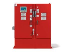
Firetrol FTA1250 Fire Pump Control can be used where the characteristics of the power source do not permit full voltage starting. The controller monitors, displays, and records fire pump system information. When the controller is actuated via pressure, START push-button, deluge valve contact, etc., the first contactor closes, connecting one of the motor windings to the line. During starting, the motor will draw approximately 65% of its normal locked rotor current and develop approximately 42% of its normal starting torque. After a time delay, the second contactor closes, connecting the second winding in parallel with the first. The motor then draws its normal running current and develops its rated torque.
Approvals: Firetrol fire pump controllers are listed by Underwriters’ Laboratories, Inc., in accordance with UL218, Standard for Fire Pump Controllers, CSA, Standard for Industrial Control Equipment, and approved by Factory Mutual. They are built to meet or exceed the requirements of the approving authorities as well as NEMA and the latest editions of NFPA 20, Installation of Centrifugal Fire Pumps, and NFPA 70, National Electrical Code.
Features
- Voltage surge protector
- Main Disconnect Switch sized for connected motor horsepower and voltage
- Fire pump Circuit Breaker
- Single Handle Isolating Disconnect Switch/Circuit Breaker mechanism
- Motor contactor
- Single Handle Emergency Manual Run Mechanism to mechanically close motor contactor contacts in an emergency condition
- Built-in Start and Stop push-buttons to bypass automatic start circuits
- Daylight Savings Time Option
- Elapsed Time Meter
- 7.0” LCD capacitive type color touch screen (HMI technology) software upgradeable operator interface powered by an embedded microcomputer with software PLC logic.
- 500 PSI Pressure Transducer (calibrated for 300 PSI (20.7 Bar))and Test Solenoid for fresh water applications, externally mounted with protective cover
- Audible alarm buzzer embedded in the MarkIII+
- Pump Room Ambient Temperature Switch, Display and Alarms
- Pressure and Event Recording with Date Stamp to System Memory Accessible VIA The User Interface and Downloadable to a USB Flash Drive
Applications
- Disconnect Switch / Circuit Breaker
- Motor Starter
- 7? Capacitive Color Touchscreen
- Weekly Test Timer
- Data Logging
- True RMS Metering
Specifications
Main Fire Pump Controller
The main fire pump controller shall be a factory assembled, wired and tested unit. The controller shall be of the combined manual and automatic type designed for full voltage starting of the fire pump motor having the horsepower, voltage, phase and frequency rating shown on the plans and drawings. The controller shall be rated for an Ambient Temperature Operating Range of 39ºF (4ºC) to 104ºF (40ºC).
Standards, Listings & Approvals
The controller shall conform to all the requirements of the latest editions of: NFPA 20, Standard for the Installation of Stationary Pumps for Fire Protection NFPA 70, National Electrical Code.
The controller shall be listed by:
Underwriters Laboratories, Inc., in accordance with UL218, Standard for Fire Pump Con- trollers Canadian Standards Association CSA-C22.2, Standard for Industrial Control Equipment (cUL)
- CE – Low Voltage Directive
- The controller shall be approved by:
- Factory Mutual (IEC 62091)
- The City of New York for fire pump service
Enclosure
The controller components shall be housed in a NEMA Type 2 (IEC IP22) drip-proof, wall mounted enclosure with bottom entry gland plate and lifting lugs.
- Withstand Ratings (Short Circuit Current Ratings)
All controller components shall be front mounted, wired and front accessible for main- tenance. The available short circuit current ratings are shown below.
| Code | 200-208V 5-150 HP | 220-240V 5-200 HP | 380-415V 5-350 HP | 440-480 5-400 HP | 550-600 5-500 HP | |||
| M – Standard | 100kA | 100kA | 100kA | 100kA | N/A | |||
| N – Intermediate | 150kA | 150kA | 150kA | 150kA | N/A | |||
| P – High | 200kA | 200kA | 200kA | 200kA | N/A | |||
| Q – Intermediate | N/A | N/A | N/A | N/A | 100kA | |||
| R – Standard | N/A | N/A | N/A | N/A | 50kA | |||
| Code | 200-208V 200 HP | 220-240V 250-400 HP | 380-415V 400-500 HP | 440-480 450-500 HP | ||||
| M – Standard | 50A | 50kA | 50kA | 50kA | ||||
| N – Intermediate | N/A | N/A | N/A | N/A | ||||
| P – High | 100kA | 100kA | 100kA | 100kA | ||||
| Q – Intermediate | N/A | N/A | N/A | N/A | ||||
| R – Standard | N/A | N/A | N/A | N/A | ||||
Power Components
The controller shall include a combination isolating disconnect switch/circuit breaker, rated for not less than 115% of the motor full load current, mechanically interlocked and operated with a single, externally mounted handle. The isolating disconnect switch/ circuit breaker shall be mechanically interlocked so that the enclosure door cannot be opened with the handle in the ON position except by a hidden tool operated bypass mechanism. The isolating disconnect switch/circuit breaker shall be capable of being padlocked in the OFF position for installation and maintenance safety, and shall also be capable of being locked in the ON position without affecting the tripping characteristics of the circuit breaker.
The controller will include a voltage surge arrestor and Part Winding motor starter. The controller shall be equipped with a single handle, manually operated, emergency start mechanism capable of being latched in the ON position.
Operator Interface (HMI)
The operator interface shall be a 7.0” LCD capacitive type color touch screen (HMI technology) powered by an embedded microcomputer with software PLC logic. In- cluded shall be keypad type push-buttons for START, STOP and TEST.
The screen shall include menus for: Home · Alarms · Configuration · History · Service · Manuals · Language.
The HMI shall graphically display the following: Voltage and Amperage of all 3 phas- es simultaneously using true RMS Technology · Motor Stopped/Running · Starting Cause · Actuation Mode · Controller Type · Shutdown Mode · Date & Time · Pump Room Temp. · System Pressure
System pressure shall be capable of being displayed as: PSI, kPa, Bar, Feet of Head or Meters of Water.
The HMI shall allow programming and display of: Cut In & Cut Out Pressure Settings · Minimum Run Timer · Sequential Start Timer · Periodic Test Timer
The HMI allows the user to select the language of the system and download the manual or view the manual on screen.
- State and Alarm Indication
Visual indication shall be provided for the following:
- Power Available
- Motor Run
- Periodic Test
- Manual Start
- Deluge Valve Start
- Remote Automatic Start
- Remote Manual Start
- Emergency Start
- Pump On Demand/Auto- matic Start
- Pump Room Temperature
- Lockout
The digital display shall visually indicate the following alarms:
- Locked Rotor Current
- Fail To Start
- Under/Over Current
- Under/Over Voltage
- Phase Unbalance
- Check Test Solenoid Valve
- Weekly Test Cut-In Not Reached
- Transducer Fault
- Control Voltage Not Healthy
- Motor Trouble
- Pump Room Alarm
- Invalid Cut-In
- Phase Reversal
- Power Loss
- Phase Loss L1 / L2 / L3
- Low Water Level
- Pump On Demand
- Low Ambient Temp.
- Service Required
Audible and visible alarm shall be provided for: Fail To Start Remote Alarm contacts shall be provided for:
- Power Available
- Phase Reversal
- Motor Run
- Common Pump Room Alarm (Overvoltage
- Under voltage
- Phase Unbalance
- Low/High Pump Room Temperature)
- Common Motor Trouble (Overcurrent, Fail To Start, Undercurrent, Ground Fault)
Pressure and Event Recording
The system shall be capable of logging pressure data and operational events with time/date stamp. The system shall display operational events for the lifetime of the controller and display the pressure data in text or graphical form. The controller shall log the Date/Time of the first start-up and the controller total power on time from that date. The controller shall log first and last statistics for: First Setup · On Time · Start Count · Last Start Time · Min/Max/Average System Pressure · Min/Max/Average Pump Room Temp. · Jockey Pump On Time/Start Count/Last Start Time · Phase to Phase Voltages with Date Stamp · Amps Per Phase with Date Stamp
USB Host Controller
A USB port capable of accepting a USB Flash Memory Disk shall be provided for downloading pressure and event logs.
Serial Communications
The controller shall feature Modbus with TCP/IP frame format and shielded female RJ45 connector
Pressure Sensing / Wet Parts
The controller shall be supplied with a solid state pressure transducer with a range of 0-500 psi calibrated for 0-300 psi (0-20.7 bar) and a run test solenoid valve. The wet parts shall be externally mounted and include a protective cover. The pressure sens- ing line connection to the transducer shall be 1/2-inch FNPT. Provisions for a redun- dant pressure transducer shall be provided.
Seismic Certification
The controller shall be certified to meet or exceed the requirements of the 2018 Inter- national Building Code, the 2019 California Building Code and OSHPD Special Seismic Certification Preapproval – OSP. The controller test criteria shall be per ICC-ES AC156 and the Seismic Parameters per ASCE 7-10 Chapter 13.
Controller Operation
The controller shall be capable of automatic starting via pressure drop, remote start signal from an automatic device or a deluge valve. The controller can be manually started via the START push-button, the RUN TEST push-button, or a remote signal from a manual device. Stopping can be achieved manually with the STOP push-button or automatically after expiration of minimum run timer or test timer. The minimum run timer (off delay), sequential start timer (on delay) and periodic test timer shall be field adjustable and include a visual countdown on the display.
For More Information and Price: Firetrol FTA1250 Fire Pump Control
Read More Articles:
- Adalet Hazlo Products and Genlo Product
- Firetrol Battery charger
- Firetrol Fire Pump Controller
- Fire Pump Test Meter GERAND Flow Meter Seri K & G, FM Approved
- Gerand Pump Test Flow Meter