
Descriptions
Brainchild Ramp Soak Controllers the Fuzzy Logic plus PID microprocessor-based profiling controller with many segments of the ramp and dwell, incorporate two bright, easy to read 4-digit LED displays, indicating process value and set point value. The Fuzzy Logic technology enables a process to reach a predetermined set point in the shortest time, with the minimum of overshoot during power-up or external load disturbance.
As a professional and experienced manufacturer, we supply high-performance and quality ramp soak controllers, which are also called programmable temperature controllers.
Brainchild Ramp Soak Controllers Feature
- Total 9 profiles, a profile with 16, 32 or 64 segments at most
- Each segment to be configured as a ramp or dwell(soak)
- Fast A-D sampling rate (5 times/s)
- After an event, the process goes to run, hold, abort, manual, failure transfer, off mode, next segment or select the second PID values
- High accuracy of 18-bit A to D input, and 15-bit D to A output
- The fast sample rate of 200 msec
- Fuzzy control to reach set point at the least overshooting and less time
- Up to three relays are configurable for event output
- Analog retransmission of process value & setpoint value
- Optional RS-485 or 232 communications
- Programmable port for easy configuration or calibration
- Lockout protection for security requirement
- Bumpless transfer of safely control while sensor breaks
- Digital filter to improve the stability of process value
- SEL function for easy operation
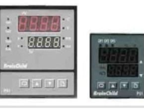
Model
- P41: 96 x 96 mm
- P91: 48 x 48 mm
Brainchild Ramp Soak Controllers Specification
power
- 90 – 250 VAC, 47 – 63 Hz, 12VA, 5W maximum
- 11 – 26 VAC / VDC, SELV, Limited Energy, 12VA, 5W maximum
Signal Input
| Resolution | 18 bits |
| Sampling Rate | 5 times / second |
| Maximum Rating | -2 VDC minimum, 12 VDC maximum( 1 minute for mA input ) |
| Temperature Effect | ±1.5 uV/ °C for all inputs except mA input ±3.0 uV/ °C for mA input |
| Sensor Lead Resistance Effect | T/C: 0.2uV/ohm 3-wire RTD: 2.6 °C/ohm of resistance difference of two leads 2-wire RTD: 2.6 °C/ohm of resistance sum of two leads |
| Burn-out Current | 200nA |
| Common Mode Rejection Ratio ( CMRR ) | 120dB |
| Normal Mode Rejection Ratio ( NMRR ) | 55dB |
| Sensor Break Detection | Sensor open for TC, RTD and mV inputs, Sensor short for RTD input, below 1 mA for 4-20 mA input, below 0.25V for 1 – 5 V input, unavailable for other inputs. |
| Sensor Break Responding Time | Within 4 seconds for TC, RTD and mV inputs, 0.1 second for 4-20 mA and 1 – 5 V inputs. |
Input
| Type | Range | ?Accuracy@ 25 °C | Input Impedance |
| J | -120 ~ 1000 °C (-184 ~ 1832 °F) | ±2 °C | 2.2M? |
| K | -200 ~ 1370 °C (-328 ~ 2498°F) | ±2 °C | 2.2M? |
| T | -250 ~ 400°C (-418 ~ 752°F) | ±2 °C | 2.2M? |
| E | -100 ~ 900 °C (-148 ~ 1652 °F) | ±2 °C | 2.2M? |
| B | 0 ~ 1800 °C (32 ~ 3272 °F) | ±2 °C (200°C – 1800°C) | 2.2M? |
| R | 0 ~ 1767.8 °C (32 ~ 3214 °F) | ±2 °C | 2.2M? |
| S | 0 ~ 1767.8 °C (32 ~ 3214 °F) | ±2 °C | 2.2M? |
| N | -250 ~ 1300 °C (-418 ~ 2372 °F) | ±2 °C | 2.2M? |
| L | -200 ~ 900 °C (-328 ~ 1652 °F) | ±2 °C | 2.2M? |
| PT100 (DIN) | -210 ~ 700 °C (-346 ~ 1292 °F) | ±0.4°C | 1.3K? |
| PT100 (JIS) | -200 ~ 600 °C (-328 ~ 1112 °F) | ±0.4°C | 1.3K? |
| mV | -8 ~ 70mV | ±0.05% | 2.2M? |
| mA | -3 ~ 27mA | ±0.05% | 70.5? |
| V | -1.3 ~ 11.5V | ±0.05% | 650K? |
Output
| Output 1 / Output 2 | |
|---|---|
| Relay Rating | 2A/240 VAC, life cycles 200,000 for resistive load |
| Pulsed Voltage | Source Voltage 5V, current limiting resistance 66? . |
| Output | |||
|---|---|---|---|
| Type | Zero Tolerance | Span Tolerance | Load Capacity |
| 4-20 mA | 3.6-4 mA | 20-21 mA | 500? max. |
| 0-20 mA | 0 mA | 20-21 mA | 500? max. |
| 0-5 V | 0 V | 5-5.25 V | 10K? min. |
| 1-5 V | 0.9-1 V | 5-5.25 V | 10K? min. |
| 0-10 V | 0 V | 10-10.5 V | 10K? min. |
| Linear Output | |
|---|---|
| Resolution | 15 bits |
| Output Regulation | 0.02 % for full load change |
| Output Settling Time | 0.1 sec. ( stable to 99.9 % ) |
| Isolation Breakdown Voltage | 1000 VAC |
| Temperature Effect | ±0.01 % of SPAN / °C |
| Triac ( SSR ) Output | |
|---|---|
| Rating | 1A / 240 VAC |
| Inrush Current | 20A for a cycle |
| Min. Load Current | 50 mA rms |
| Max. Off-state Leakage | 3 mA rms |
| Max. On-state Voltage | 1.5V rms |
| Insulation Resistance | 1000 Mohms min. at 500 VDC |
| Dielectric Strength | 2500 VAC for 1 minute |
| DC Voltage Supply characteristics(Install at Output2) | ||||
|---|---|---|---|---|
| Type | Tolerance | Max. Output Current | Ripple Voltage | Isolation Barrier |
| 20V | ±1V | 25mA | 0.2Vp-p | 500VAC |
| 12V | ±0.6V | 40mA | 0.1Vp-p | 500VAC |
| 5V | ±0.25V | 80mA | 0.05Vp-p | 500VAC |
Alarm
| Alarm Relay | Form C, Max. rating 2A/240VAC, life cycles 200,000 for resistive load. |
| Alarm Functions | Dwell timer, Deviation High / Low Alarm, Deviation Band High / Low Alarm PV High / Low Alarm |
| Alarm Mode | Normal, Latching, Hold, Latching / Hold. |
| Dwell Timer | 0.1 – 4553.6 minutes |
Data Communication
| Interface | RS-232 ( 1 unit ), RS-485 ( up to 247 units ) |
| Protocol | Modbus Protocol RTU mode |
| Address | 1 – 247 |
| Baud Rate | 2.4 ~ 38.4 Kbits/? |
| Parity Bit | None, Even or Odd |
| Stop Bit | 1 or 2 bits |
| Communication Buffer | 64 bytes |
Analog Retransmission
| Output Signal | 4-20 mA, 0-20 mA, 0-1V, 0-5V, 1-5V, 0-10V |
| Resolution | 15 bits |
| Accuracy | ±0.05 % of span ±0.0025 %/ °C |
| Load Resistance | 0 – 500 ohms ( for current output ),10 K ohm minimum ( for voltage output ) |
| Output Regulation | 0.01 % for full load change |
| Output Settling Time | 0.1 sec. (stable to 99.9 % ) |
| Isolation Breakdown Voltage | 1000 VAC min. |
| Integral Linearity Error | ±0.005 % of span |
| Temperature Effect | ±0.0025 % of span/ °C |
| Saturation Low | 0 mA ( or 0V ) |
| Saturation High | 22.2 mA ( or 5.55V, 11.1V min. ) |
| Linear Output Range | 0 – 22.2mA(0-20mA or 4-20mA), 0 – 5.55V ( 0 – 5V, 1 – 5V ), 0 – 11.1 V ( 0 – 10V ) |
| User Interface | Dual 4-digit LED Displays |
|---|---|
| Keypad | 4 keys |
| Programming Port | For automatic setup, calibration, and testing |
| Communication Port | RS-232 and RS-485 |
| Control Mode | |
|---|---|
| Output 1 | Reverse ( heating ) or direct ( cooling )action |
| Output 2 | PID cooling control, cooling P band 50 ~ 300% of PB, dead band -36.0 ~ 36.0% of PB |
| ON-OFF | 0.1 – 90.0 ( °F ) hysteresis control ( P band = 0 ) |
| P or PD | 0 – 100.0 % offset adjustment |
| PID | Fuzzy logic modified, Proportional band 0.1 ~ 900.0°F, Integral time 0 – 1000 seconds , Derivative time 0 – 360.0 seconds |
| Cycle Time | 0.1 – 90.0 seconds |
| Manual Control | Heat (MV1) and Cool (MV2) |
| Auto-tuning | Cold start and warm start |
| Failure Mode | Auto-transfer to manual mode while sensor break or A-D converter damage |
| Ramping Control | 0 ~ 900.0°F/minute or 0 ~ 900.0 °F/hour ramp rate |
| Digital Filter | |
|---|---|
| Function | First order |
| Time Constant | 0, 0.2, 0.5, 1, 2, 5, 10, 20, 30, 60 seconds programmable |
| Profiler | |
|---|---|
| Number of profiles | 9 |
| Number of Segment per profile | Profile 1,2,3,4 : 16 Profile 5,6,7: 32 Profile 8,9 : 64 |
| Event Outputs | 3 |
Environmental & Physical
| Operating Temperature | -10°C ~ 50°C |
| Storage Temperature | -40°C ~ 60°C |
| Humidity | 0 to 90 % RH ( non-condensing ) |
| Altitude | 2000m maximum |
| Pollution | Degree 2 |
| Insulation Resistance | 20 Mohms min. ( at 500 VDC ) |
| Dielectric Strength | 2000 VAC, 50/60 Hz for 1 minute |
| Vibration Resistance | 10 – 55 Hz, 10 m/s² for 2 hours |
| Shock Resistance | 200 m/s² ( 20 g ) |
| Moldings | Flame retardant polycarbonate |
| Dimensions | P41 —96mm(W) X 96mm(H) X 65mm(D), 53 mm depth behind panel P91 —48mm(W) X 48mm(H) X 116mm(D), 105 mm depth behind panel |
| Weight | P41 — 250 grams P91 — 150 grams |
| Approval Standards | UL 61010C-1 , CSA C22.2 No. 24-93 , EN61010-1 (IEC1010-1) |
Protective Class
- IP65 front panel with an additional option,
- IP50 front panel without additional option,
- all indoor use,
- IP 20 housing and terminals with protective cover.
EMC: EN61326