
Static Liquid and Gas Mixer
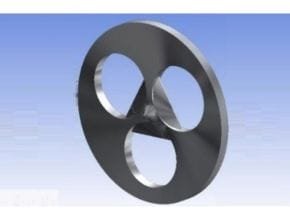
When pipeline space is limited for installing a traditional static mixer, the patented Komax Wafer Type Static Mixer solves space and mixing problems. The Wafer mixer can be installed between the two pipe flanges in the main water stream.
Komax Wafer Static Mixer offers advantages over traditional mixers:
- Designed to clamp between existing pipe flanges
- Allows up to three injection ports
- Uses patented vortex generating element technology
- Clog-resistant counter-flow injection
- Sizes available from 4? to 60? nominal diameter
- Available in standard materials of construction: Carbon Steel, Stainless Steel, PVC, FRP, and can also be made out of titanium or specialty alloys as required
- Low capital cost, no moving parts, maintenance-free, low head loss, and long service life
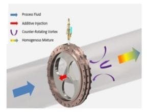
Komax Wafer Mixer technology employs a unique vortex generating element group1 that helps achieve a desirable mixing quality by creating three-way counter-rotating vortex pairs as compared to typical energy-inefficient two-way mixers in the market.
Extensive studies were carried out to determine optimal design parameters of the element such as height and inclination angle, which offers short mixing length with low-pressure loss in various flow conditions.
The additive chemical is introduced in the centerline of the mixer on the upstream side. A discharge cone2 enables the injected chemical to be distributed evenly through the three vortex-inducing passages. The pressure difference between the front and rear side of each element produces reversed flow that carries the chemical back toward the rear side of the mixer where intensive mixing occurs by the resulting vortical structure from the distinctive three-way counter-rotating vortex pairs.
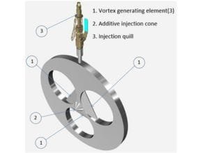
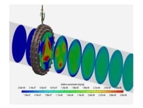
Fig 2. CFD analysis of 30” wafer mixer installed in Riverside, CA. Proven to achieve a CoV of 0.05 or lower.
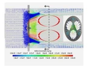
Fig 3. Velocity vector profile colored in an additive chemical concentration
In terms of the pressure loss, this unique wafer mixer design reduces the energy loss of the flow through the mixer as more flow remains attached to the mixer walls preventing the flow separation compared to other conventional mixers.
Typical Assembly Schematic
Typical Wafer Mixer Applications
Use the following three simple steps to solve most turbulent flow mixing problems
- Waste Water Flocculation
- Water/ Waste Water pH control
- Water/ Waste Water Dechlorination
- Water Chloramination
- Mixing any other additives into water
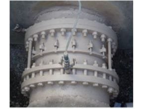
Fig 5. 30” Wafer mixer installed between flanges
Read More Article:
- Static Mixer
- KOMAX MOTIONLESS MIXER – CHANNEL (SQUARE)
- KOMAX TRIPLE ACTION STATIC MIXER
- Koflo Clear PVC Static Mixer
- Fcon CUBE GM-X? series Touch Panel Gas Mixer with Buffer tank specification
- Fcon CUBE GM-X Series Touch panel Gas Mixer
- Impellers and Propellers Mixer and Agitator