
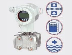
Keradiff 100 Intelligent Differential Pressure Transmitter has a robust, highly overload-resistant silicon sensor with an outstanding capacity for high measuring accuracy, vacuum resistance, and reliability for all long-term stable measurements. The high-performance measuring system is used to measure differential pressure, filling levels and flow, in connection with differential pressure transmitters, for gases, vapors and liquids. The devices are suitable for differential pressure as well as for positive and negative overpressure.
Medium- and process-suitable materials as well as different design variants allow the use of these devices with corrosive or abrasive media, as well as for processes with high aseptic requirements (e.g. in the food or pharmaceutical industry). Flush-mounted versions and pressure transmitters for almost all process connections are available for filling-level applications.
Keradiff 100 Intelligent Differential Pressure Transmitter various types of measuring cells for graded measuring ranges ranging from 10 bar, PN 160 bar, to 40 bar, PN 420 bar, thus allowing for optimal adaptation to the process conditions. The digital communication signal (HART® protocol) can be superimposed onto the 4…20 mA signal and offers all information required for teleparametrisation (smart technology), as well as the version with the Profibus PA.
Keradiff 100 Intelligent Features:
- for measuring differential pressure, filling levels and flow
- rapid use as a result of comfortable and simple operation
- 4…20 ma, Hart® or Profibus output
- measuring ranges from 1 mbar to 40 bar
- high measuring accuracy < 0.1%
- turndown 100 : 1
- various process connections
Keradiff 100 Intelligent Specification:
General Information | ||
| Device type | KERADIFF | |
| Application | Differential pressure measurement | |
| Measuring sensor | Silicon sensor | |
Output | ||
| Output signal | 4…20 mA with superimposed HART® protocol or PROFIBUS PA | |
| Breakdown signal | 3.6 mA minimum alarm, 21 mA maximum alarm | |
| Current limit | 3.8 mA; 20.5 mA | |
| Resolution | Current output: 1µA | |
| Display: adjustable | ||
Measuring accuracy | ||
| Influence of the system pressure on the zero point range | 0.2% / 100bar | |
| Thermal change | ± 0.2% for -40..-10°C or +60…+85°C | |
| Temperature coefficient for zero signal or output range | 0.02% / 10K (-10…+60 °C) and | |
| 0.1% / 10K (-40…-10 °C or +60…85°C) | ||
| Temperature coefficient of the pressure transmitter | see pressure transmitter table for TK of the zero point | |
| Deviation from the characteristic curve: | max. 0.1% | |
| max. 0.2% for the measuring limit range | ||
| Hysteresis: | 0.1% of the set range | |
| Repeatability: | 0.1% of the set range | |
| Heating time: | 4…20 mA HART® < 10s, PROFIBUS PA 6s | |
| Setting time: | between 0.5 and 2s, depending on the measuring range | |
| Rise: | between 0.4 – 1.6s, depending on the measuring range | |
| Long-term drift | 0.2% / a | |
| Adjustable attenuation | 0…999s, adjustable via on-site operating field or PC (factory setting: 2s) | |
| Conditions for use | ||
| Medium temperature | -40…+85 °C | |
| Nominal temperature | -40…+85 °C | |
| Operating temperature | -40…+85 °C | |
| -20…+70 °C with on-site display | ||
| Storage temperature | -40…+100 °C | |
| -40…+85 °C on-site display | ||
| Protective class according to EN 60529 | IP 67 | |
| Electromagnetic compatibility (EMV) | Electromagnetic compatibility according to EN 61326 and NAMUR recommendation EMV | |
| (NE21) | ||
| Vibration strength | ± 0.1% according to DIN/IEC 68, Part 2-6, based on sensor range, measured on a 6000 | |
| mbar sensor | ||
| Installation position | Any, compensation when calibrating the measuring start | |
| Auxiliary energy | ||
| Supply voltage | 11.5…45V | |
| Residual ripple | No influence for 4…20 mA signal up to ± 5% residual ripple | |
| Design configuration | ||
| Materials | Housing: | Copper-free die-cast aluminium housing with a protective coating on a |
| polyester basis, grey, resistant to seawater, salt-spray test DIN 50 021 (504 | ||
| hours) passed, optional process connection, O-rings made from NBR for | ||
| cover sealing, assembly bracket made from C22.8 | ||
| Membrane: | AISI 316 L | |
| Flange: | DIN 19213 from AISI 316 L | |
| For KERADIFF 140, 150: | ||
| Pressure transmitter from AISI 316 L, see corresponding data sheets, special materials | ||
| a..A: | ||
| Capillary tube and holding pipe made of AISI 316 L | ||
| KERADIFF 150: Installation of the pressure transmitter: rigid connection via holding flange | ||
| required | ||
| Process connections | All standard and common connections (see dimensional drawings) | |
| Electrical connection | M20x1,5 | |
| Terminal connection with a built-in inter-clock diode for cable diameters of 0.5 to 2.5 mm², | ||
| two-wire connection cable with a standard installation cable. | ||
| Climate class | Class 4K4H (air temperature: -20…+55°C, relative humidity: 4…100%) according to DIN | |
| EN 60721-3-4 fulfilled (condensation possible) | ||
Electrical Connection Keradiff 100 Intelligent Differential Pressure Transmitter
- Housing
- Jumper for 4…20 mA test signal
- Internal earth terminal
- External earth terminal
- 4…20 mA test signal between the plus and test terminal
Minimum voltage supply = 10.5 V DC, jumper is attached
according to the diagram- Minimum voltage supply = 11.5 V DC, jumper is attached in
“test” position
Devices with integrated overvoltage protection are labeled
with “OVP” (overvoltage protection) at this point.
Download Data Sheet: Keradiff 100 – Intelligent Differential Pressure Transmitter
Ref: hengesbach.com
Another Article:
- Hengesbach Keradiff 150 Differential Pressure Transmitter
- Hengesbach Pressure Measurement
- Quantum 2+ Pulsar Intelligent Pumping Station Controller
- Alia Electromagnetic Flow Meter
- Additel Instruments Intelligent Digital Pressure Modules Additel 160A Series