
Overview
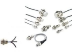
Omron 3 Wire Proximity Sensor uses high-frequency oscillation. They resist heat, chemicals, and water better than Rectangular Sensors. They are available in both shielded and unshielded models.
Proximity Sensors are available in models using high-frequency oscillation to detect ferrous and non-ferrous metal objects and in capacitive models to detect non-metal objects. Models are available with environment resistance, heat resistance, resistance to chemicals, and resistance to water.
Omron E2E-X DC Model 3 Wire Proximity Sensor
Features and Benefits
- Standard Sensors for detecting ferrous
- A wide array of variations. Ideal for a variety of
- Models with different frequencies are also available to prevent mutual
- Superior environment resistance with standard cable made of oil-resistant PVC and sensing surface made of a material that resists cutting
- Useful to help prevent
- Cable protector provided as a standard feature
Ratings and Specifications
| Size Shielded | M8 | M12 | M18 | M30 | |||||
| Shielded | Unshielded | Shielded | Unshielded | Shielded | Unshielded | Shielded | Unshielded | ||
| Item Model | E2E | E2E | E2E | E2E | E2E | E2E | E2E-X10E@/ | E2E | |
| -X1R5E@/F@ | -X2ME@/F@ | -X2E@/F@ | -X5ME@/F@ | -X5E@/F@ | -X10ME@/F@ | F@ | -X18ME@/F@ | ||
| Sensing distance | 1.5 mm ±10% | 2 mm ±10% | 5 mm ±10% | 10 mm ±10% | 18 mm ±10% | ||||
| Set distance | 0 to 1.2 mm | 0 to 1.6 mm | 0 to 4 mm | 0 to 8 mm | 0 to 14 mm | ||||
| Differential travel | 10% max. of sensing distance | ||||||||
| Detectable object | Ferrous metal (The sensing distance decreases with non-ferrous metal. Refer to Engineering Data on page 18.) | ||||||||
| Standard sensing object | Iron, | Iron, 12 ´ 12 ´ 1 mm | Iron, | Iron, | Iron, 30 ´ 30 ´ 1 mm | Iron, | |||
| 8 ´ 8 ´ 1 mm | 15 ´15 ´ 1 mm | 18 ´ 18 ´ 1 mm | 54 ´ 54 ´ 1 mm | ||||||
| Response frequency | 2 kHz | 0.8 kHz | 1.5 kHz | 0.4 kHz | 0.6 kHz | 0.2 kHz | 0.4 kHz | 0.1 kHz | |
| Power supply voltage (operating voltage range) *2 | 12 to 24 VDC, ripple(p-p): 10% max. (10 to 30 VDC) | ||||||||
| Connector Models Used as UL-certified Models: 12 to 24 VDC, ripple (p-p): 10% max. (The operating voltage range is also the same.) *3 | |||||||||
| Current consumption | 13 mA max. | ||||||||
| 200 mA max. | |||||||||
| Control output | 2 V max. (Load current: 200 mA, Cable length: 2 m) | ||||||||
| Indicators | Operation indicator (red) | ||||||||
| Operation mode (with sensing object approaching) | E1/F1 Models: NO E2/F2 Models: NC | ||||||||
| Refer to the timing charts under /O Circuit Diagrams on page 21 for details. | |||||||||
| Protection circuits | Load short-circuit protection, Surge suppressor, Reverse polarity protection | ||||||||
| Ambient temperature range *2 | Operating/Storage: -40 to 85°C (with no icing or condensation) | ||||||||
| Ambient humidity range | Operating/Storage: 35% to 95% (with no condensation) | ||||||||
| Temperature influence | ±15% max. of sensing distance at 23°C in the temperature range of -40 to 85°C | ||||||||
| ±10% max. of sensing distance at 23°C in the temperature range of -25 to 70°C | |||||||||
| Voltage influence | ±1% max. of sensing distance at rated voltage in the rated voltage ±15% range | ||||||||
| Insulation resistance | 50 MÙ min. (at 500 VDC) between current-carrying parts and case | ||||||||
| Dielectric strength | 1,000 VAC, 50/60 Hz for 1 minute between current carry parts and case | ||||||||
| Vibration resistance | Destruction: 10 to 55 Hz, 1.5-mm double amplitude for 2 hours each in X, Y, and Z directions | ||||||||
| Destruction: 500 m/s2 | |||||||||
| Shock resistance | 10 times each in X, Y, and Z directions | Destruction: 1,000 m/s2 10 times each in X, Y, and Z directions | |||||||
| Degree of protection | Pre-wired Models: IEC 60529 IP67, in-house standards: oil-resistant Connector Models: IEC 60529 IP67 | ||||||||
| Connection method | Pre-wired Models (Standard cable length: 2 m) and Connector Models | ||||||||
| Weight (packed state) | |||||||||
| Pre- wired Models | Approx. 65 g | Approx. 75 g | Approx. 150 g | Approx. 195 g | |||||
| Connec- tor Models | Approx. 15 g | Approx. 25 g | Approx. 40 g | Approx. 90 g | |||||
| Case | Stainless steel (SUS303) | Nickel-plated brass | |||||||
| Sensing surface | PBT | ||||||||
| Clamp- ing nuts | Nickel-plated brass | ||||||||
| Materials | Toothed washer | Zinc-plated iron | |||||||
| Accessories | Instruction manual | ||||||||
Omron E2EM-X@C@ DC Long distance Proximity Sensor
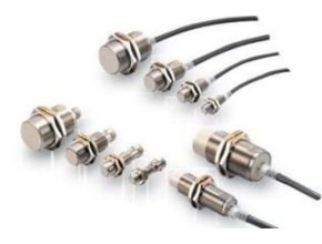
Features
- Long-distance detection at up to 30 mm enables secure mounting with reduced problems due to workpiece
- No polarity for easy wiring with DC 2-wire
- Cable protector provided as a standard
Specifications
| Size Shielded | M8 | M12 | M18 | M30 | |
| Shielded | Shielded | Shielded | Shielded | ||
| Item Model | E2EM-X2C@(-M1) | E2EM-X4C@(-M1) | E2EM-X8C@(-M1) | E2EM-X15C@(-M1) | |
| Sensing distance | 2 mm ±10% | 4 mm ±10% | 8 mm ±10% | 15 mm ±10% | |
| Set distance | 0 to 1.6 mm | 0 to 3.2 mm | 0 to 6.4 mm | 0 to 12 mm | |
| Differential travel | 10% max. of sensing distance | ||||
| Detectable object | Ferrous metal (The sensing distance decreases with non-ferrous metal. Refer to Engineering Data on page 4.) | ||||
| Standard sensing object | Iron, 8 ´ 8 ´ 1 mm | Iron, 12 ´ 12 ´ 1 mm | Iron, 18 ´ 18 ´ 1 mm | Iron, 30 ´ 30 ´ 1 mm | |
| Response frequency *1 | 1.5 kHz | 0.5 kHz | 0.3 kHz | 0.1 kHz | |
| Power supply voltage (operating voltage range) *2 | 12 to 24 VDC (10 to 30 VDC), ripple (p-p): 10% max. | ||||
| Current consumption | 13 mA max. | ||||
| Control output | Load current *2 | 200 mA max. | |||
| Residual voltage | 2 V max. (Load current: 200 mA, Cable length: 2 m) | ||||
| Indicators | Operation indicator (yellow) | ||||
| Operation mode (with sens- ing object approaching) | C1 Models: NO Refer to the timing charts under I/O Circuit Diagrams on page 5 for details. C2 Models: NC | ||||
| Protection circuits | Reverse polarity protection, Load short-circuit protection, Surge suppressor | ||||
| Ambient temperature range | Operating: -25 to 70°C Storage: -40 to 85°C (with no icing or condensation) | ||||
| *1 | Operating/Storage: -40 to 85°C (with no icing or condensation) | ||||
| Ambient humidity range | Operating/Storage: 35% to 95% (with no condensation) | ||||
| Temperature influence | ±15% max. of sensing distance at 23°C in the temperature range of -40 to 85°C | ±15% max. of sensing dis- tance at 23°C in the temperature range of -25 to 70°C | |||
| ±10% max. of sensing distance at 23°C in the temperature range of -25 to 70°C | |||||
| Voltage influence | ±1% max. of sensing distance at rated voltage in the rated voltage ±15% range | ||||
| Insulation resistance | 50 MÙ min. (at 500 VDC) between current-carrying parts and case | ||||
| Dielectric strength | 1,000 VAC, 50/60 Hz for 1 minute between current-carrying parts and case | ||||
| Vibration resistance | Destruction: 10 to 55 Hz, 1.5-mm double amplitude for 2 hours each in X, Y, and Z directions | ||||
| Shock resistance | Destruction: 500 m/s2 10 times each in X, Y, and Z directions | Destruction: 1,000 m/s2 10 times each in X, Y, and Z directions | |||
| Degree of protection | Pre-wired Models: IEC 60529 IP67, in-house standards: oil-resistant Connector Models: IEC 60529 IP67 | ||||
| Connection method | Pre-wired Models (Standard cable length: 2 m) Connector Models | ||||
| Weight (packed state) | Pre-wired Models | Approx. 65 g | Approx. 75 g | Approx. 150 g | Approx. 195 g |
| Connector Mod- els | Approx. 15 g | Approx. 25 g | Approx. 40 g | Approx. 90 g | |
| Case | Stainless steel (SUS303) | Nickel-plated brass | |||
| Sensing surface | PBT | ||||
| Clamping nuts | Nickel-plated brass | ||||
| Materials | Toothed washer | Zinc-plated iron | |||
| Accessories | Instruction manual | ||||
*1. The response frequency is an average value.
Measurement conditions are as follows: standard sensing object, a distance of twice the standard sensing object, and a set distance of half the sensing distance.
*2. When using an M8 Model at an ambient temperature between 70 and 85°C, supply 10 to 30 VDC to the Sensor and make sure that the Sensor has a control output of 100 mA maximum.
Download Catalog: Long-distance Proximity Sensor E2EM
Ref: Omron.com
Another Article:
- Omron E2EY Alumunium Detecting Proximity Sensor
- ONICON- F2600 Series Inline Vortex Flow Meter
- Signet 2000 Micro Flow Sensor
- OBL Blackline R Series Plunger Metering Pumps
- Pressure Switch 132 P Series
- MarelliMotori Series Motors Marine A_M – B_M
- Gastec WPT-132 Waste Water Test Kit
- Trafag TFS Float Level Switch
- APG HU-1502 Hammer Union Pressure Transmitter
- Microsensor Corp MDM390 Differential Pressure Transmitter