
General Information
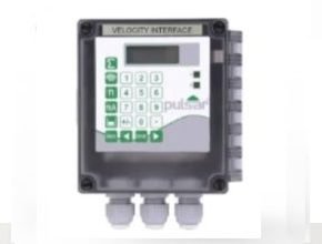
Pulsar Velocity Interface Wall Mounted is a digital-to-analog converter that works with the latest Speedy velocity sensor in two important ways. It frees up the RS485 output from a FlowCERT controller in applications where digital communications are required and allow users of Pulsar’s older equipment to upgrade to the latest Speedy sensor. It also provides the option of alarms based on flow velocity.
The Velocity Interface controller is very easy to use and may be calibrated quickly and simply via the on-board keypad and display, or alternatively by using the optional handheld calibrator, which connects to the unit via the RS232 interface and provides an on-board LCD display.
Pulsar’s new FlowCERT system gives you everything you need for the very highest accuracy non-contacting ultrasonic measurement of open channel flows. Designed for flumes and weirs, FlowCERT gives temperature-independent, reliable measurement and high
capacity logging facilities.
FlowCERT controller includes five alarm/control relays plus 4-20mA output, data logging, and digital input with the ability to accept a velocity sensor input if required (see over). Programming the unit is a simple, menu-driven process and, as standard, calculations for a wide
range of flumes and weirs. FlowCERT performs a fully implemented calculation to BS3680, and 32-point linearisation is also included.
Pulsar Velocity Interface Wall-Mounted Features
- Allows modbus or profibus comms when using speedy sensor
- Gives backward compatibility to previous Speedy units
Specifications
Physical
| Sensor body dimensions: | 130 x 150 x 63.5mm (5.12 x 5.9 x 2.5in) |
| Sensor body weight: | Nominal 0.65kg (1.4lbs) |
| Enclosure material/Description: | Polycarbonate, flammability rating UL91-V0 (UV stabilized) |
| Cable entry detail: | Underside fitted with 3x M20, nylon cable glands for 6-12mm cable |
| Transducer cable extensions: | 4-core screened |
| Maximum separation: | Up to 100m (328ft) |
Environmental
| Enclosure protection: | IP66/67 |
| Max. and min. temperature (electronics): | -20°C to +50°C (-4°F to +120°F) |
Approvals
| CE approval: | Listed in the Certificate of Conformity within the manual |
Performance
| Min. & max. range: | 6m/s to 6m/s. Dependent on the sensor used |
Outputs
| Analog output: | Isolated passive output (active output optional) of 4-20mA or 0-20mA into 1k? (user programmable and adjustable) 1% resolution |
| Serial port: | RS232 for programming and data extraction |
| Volt free contacts, number & rating: | 2 form “C” (SPDT) rated at 2A at 240Vac |
| Display: | 2 x 12 alphanumeric |
Programming
| On-board programming (standard): | By integral keypad |
| Remote programming (optional): | Via RS232 using an optional handheld calibrator |
| Programming security: | Via passcode (user selectable and adjustable) |
| Programmed data integrity: | Via non-volatile RAM |
Supply
| Power supply: | 115Vac +5% / -10% 50/60Hz, 230Vac +5% / -10% 50/60Hz, 10-24Vdc, 10W maximum power (typically 5W) |
| Fuses: | 50mA at 200-240Vac, 100mA at 90-120Vac |
| Remote communicator power supply: | Via RS232 interface |
MicroFlow provides a non-contacting, velocity measurement solution for open channels. Use MicroFlow as a stand-alone device for simple velocity measurement or pair it with a dB Ultrasonic Transducer for a complete area-velocity system. Area-velocity calculations using MicroFlow provide a cost-effective flow measurement solution compared to the installation of a Primary Measuring Device (PMD). Additionally, the hydraulics of a site can sometimes not allow for restriction within the channel, therefore it would be unsuitable for a PMD to be installed, the MicroFlow provides a viable solution.
Area-Velocity Measurement for Channels <1.5 Meter Wide
For channels less than 1.5 m (4.9 ft) wide, MicroFlow can be combined with the dBMACH3 flow transducer (or another dB Transducer) and a FlowCERT controller to gain accurate area-velocity readings.
Area velocity for Channels >1.5 Meter Wide
For larger channels such as rivers or effluent flow channels that are more than 1.5 m (4.9 ft) wide, more than one MicroFlow should be used to provide improved measurement, averaged across the wider flow profile, with the selected dB Transducer and an Ultimate Controller for an area-velocity flow system that averages the velocity from multiple sensors across the channel, ensuring accuracy in difficult to achieve straight-run conditions.
Software & Technology
The MicroFlow sensor uses K-Band radar technology and Pulsar Measurement’s unique analysis software takes readings from the whole width of the channel. Iif more than one MicroFlow is being used, an average reading will be calculated back in the control unit. To gain the most accurate and reliable reading, the end-user should make sure that the MicroFlow unit is mounted at 45 degrees to the water surface.
The K-Band radar technology works by using short pulses of microwaves, which are transmitted by an enclosed antenna on the face of the unit. When reflected off a moving surface, the signal experiences a shift in frequency characteristics. The reflected signal is captured by the onboard microprocessor via the antenna and analyzed to determine the velocity.
Download Datasheet: Velocity Interface Pulsar Wall-mounted Velocity Measurement Controller
Reference : pulsar-pm.com
Another Article:
- Fluidwell F124 Ratio Controller
- KEPmeter 52U Multipurpose Device: Counter, Rate Meter and Timer
- Fluidwell F127 Differential Flow Computer
- Fluidwell F126-EG Flow Computer
- Onicon System-10 BTU Meter