
Description
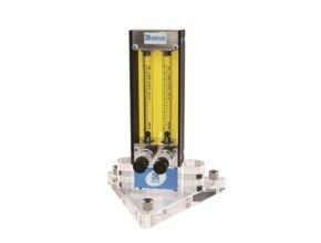
Kofloc RK120X Series Multiple Flow Meter with Needle Valve is made by combining several types of flow meter for controlling various flows in a laboratory. It is designed based on the Flowmeter Kofloc RK 120X, a flow meter with a precision needle valve, and has been verified to have outstanding reliability.
The flow meter (area type flow meter) has a float inside a conical cylinder (tapered tube) with the upper end larger than the lower end. The float moves up and down according to the intensity of flow, and the reading is taken when the float balances indicate the flow rate. KOFLOC provides flow meters with a valve that can perform both measurement and control of the flow rate, flow meters with an alarm function, and many other products.
The Principles of Flow Meter Float Type
As shown in the figure, the area (float type) flow meter has a conical cylinder (tapered tube) with the upper end larger than the lower end, having a float inside. The float moves up and down according to the flow, and the reading taken when it balances indicates the flow rate.

The symbols and units are determined as follows:
- Vf: Volume of float [cm3]
- ?f: Density of float [g/cm3]
- af: Maximum cross-section of float [cm2]
- P1: Pressure directly under float [Pa]
- P2: Pressure directly above float [Pa]
- ?: Flow density [g/cm3]
- U1: Flow velocity directly under float [cm/sec]
- U2: Flow velocity in float clearance [cm/sec]
- A1: Cross section directly under float [cm2]
- A2: Cross section of float clearance [cm2]
- Q: Flow rate [cm3/sec]
- g: Gravitational acceleration
- The force that pushes up the float is af (P1–P2). Subtracting the buoyancy, the gravitation of the float is Vf (?f–?) g.
Flow rate when load pressure is applied (Measurement of gas)1.
As shown in Figure A, the float-type flow meter is generally used with the rear section of the fl ow meter exposed to the atmosphere or without any load (without pressure loss resistance). The scale of such a flow meter is called the “atmospheric scale.”

Flow rate when load pressure is applied (Measurement of gas) 2.
The scale of such a flow meter is called the “atmospheric scale.” In fact, however, there often exists load pressure resistance as shown in Figure B. As shown in the example of the principle, load pressure resistance does not allow the actual flow rate to be indicated. There is a method to find a rough standard using the equation for calculation, but some errors will be caused because of the gap between theory and practice. Such an error will be caused both in the pressurized condition and in the vacuum condition.

For example, the flow control valve and the like are arranged in the later stage as shown in Figure C to control the pressure applied to the flow meter with a pressure regulator or the like. The scale of the flow meter is calibrated under that pressure condition. The scale of such a flow meter is called a “load pressure scale.” An example of using the load pressure scale is our GM Series gas mixing equipment. In the GM Series, the basic flow sheet is used as shown in Figure C so that the gas obtained with a constant flow rate will be pressurized.
The load pressure scale of a flow meter with a valve on the outlet side (needle, etc. on top of RK-1250) is automatically calibrated at all times, but if the flow meter will be used independently, please inform us of this in advance and select the Panotation. An extra charge will be added for load pressure calibration.

The upper section of a fl ow meter is on the outlet side, while the lower section is on the inlet side.
The equivalent flow chart of the upper and lower valves is shown in the figure.
The pressure loss of a flow meter is very small, not causing any problems when a flow meter is used individually. In the case of a flow meter with a valve, however, the inlet side pressure and outlet side pressure are important. The valve installed in a flow meter causes a pressure loss, generating a difference between the inlet pressure and outlet pressure. As shown on page 50, the reading of a float-type flow meter differs according to the applied pressure.
Therefore, for flow meters with a valve, care is needed to see what will be the applied pressure. In such cases, the inlet pressure P1 is throttled by a needle valve, changing into P2 at the outlet. n the lower section, this P2 is the pressure applied to the flow meter. When there is no significant load resistance (similar to atmospheric conditions) at the outlet and the subsequent section, P2 can be regarded as 0 MPa · G (gauge pressure), and as no pressure is applied to the flow meter, a general flow meter is used for calibration. (Refer to the atmospheric scale on page 50.) Since operating pressure conditions are necessary for valves, however, it is necessary to clearly indicate P1 and P2 when placing an order. Please indicate P2 as well when there is load resistance (when P2 pressure exists).

In the case of the upper valve, the inlet pressure P1 is applied to the flow meter.
In that case, P1 and P2 are necessary when selecting a valve as mentioned above, and the scale of the flow meter should be the negative pressure scale (P.50) of P1. Therefore, the pressure is controlled by a pressure regulator so that P1 will not change while us-ing a flow meter in general. Especially, when pressure is reduced to a vacuum in the rear stage, the flow reading will be incorrect unless an upper valve type, which reduces pressure P1 so that the flow meter will not be decompressed, is used. Care is needed.

The Principle of Rotameter with Needle Valve
KOFLOC is a general manufacturer of precision flow measuring and precision flow control instruments. By combining these two technologies, we manufacture float-type flow meters with various valves. For flow control, the flow must be measured almost all the time. Assembling a valve and a flow meter separately and then combining them may have some merits in terms of specifications, but flow meters with a valve have more merits in terms of piping labor, mounting space, and the possibility of general adjustment.
To meet such needs, KOFLOC manufactures flow meters with various types of valves, as represented by the flow meter with a needle valve. Flow meters with a needle valve are subdivided into the simple type, precision type, large-capacity type, and bellows type, as well as models with a valve on the inlet side or on the outlet side.
In addition, flow meters with a variable primary pressure type flow controller, flow meters with a variable secondary pressure type flow controller, and flow meters with a sophisticated control valve are also available. Most valves attached to these flow meters are basically identical to the flow control valves shown under different headings.
Kofloc RK120X Features
- Multiple control of two to four flow meters can be attached to one unit to permit the control of various gases in various flow ranges.
- Various flow ranges Flow meter Kofloc RK 120X
- The flow meter can measure a variety of flows ranging from the very small flow of full-scale 5 ML/MIN to 20 L/MIN.
- High-precision measurement and control
- This flow meter is designed based on the precision flow meter RK1200 and permits control of very small flow and high-precision measurement (FS ±2%).
Applications Flow meter Kofloc RK 120X
- Control of multiple components
- Multiple range control
- Flow control in laboratories
Standard Specifications Flow meter Kofloc RK 120X
| Fluids | Air,N2,O2,H2,He,Ar,CO2 (Calibration with actual gas) For other gases, please consult us regarding conversion conditions or calibration with the actual gas to be used. | |
| Flow range | From 0.5–5 ML/MIN to 2–20 L/MIN | |
| (Refer to the Capacity Table on page 55.) | ||
| Accuracy | FS ±2% (Measurement point) | |
| * Optional: FS ±1% (Measurement point) | ||
| Proof pressure | 0.5MPa | |
| Available scale | 10:1 * Optional 20:1 | |
| Material | SS | BS |
| Body block | SUS316 | Brass |
| Tapered tube | Pyrex®, glass | |
| Packing | FKM, * Option (1) | NBR |
| Float | Pyrex, SUS316, glass | |
| Protective cover | Acrylic resin | |
| Temperature resistance | MAX60? | |
| Connection | Rc 1/4 (Standard), Rc 1/8 (Optional) | |
Source : kofloc.co.jp
Other Articles:
- Kofloc Mass Flow Controller D8500 Series
- Kofloc RK1450 High Precision Flow Meter for Sensitive Measurement
- Kofloc RK120X Rotameter
- Kofloc RK120XM Series Flow Meter for Gas Mixing
- Bamo Needle Valve A 32
- Flow Control Valve Kofloc
- Kofloc Model 3760 Series
- Kofloc Back Pressure Valve Model 6801 Series
- Differential Pressure Flow Meter
- Kofloc Mass Flow Meter and Controllers
- Rotameter Kofloc RK1930/RK1935
- Kofloc CK Series Flow Setting Device Model
- Kofloc 2600 All-Teflon Constant Flow Control Valve
- Kofloc 3660 Series Mass Flow Controller
- Kofloc Model DPM-3 Flow Indicators
- Kofloc FM31 Series Small Karman Vortex Flowmeter
- Kofloc 8500 Series Mass Flow Meter