
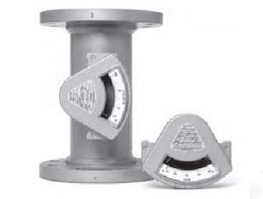
Edrco See-flow 3100 Sight Flow Indicators show you at a glance, the color, clarity, and flow of liquids in process lines. The large tempered glass window permits easy observation of fluid conditions and vane indicator position. The wedge shape of the meter housing makes See-Flo® practically self-cleaning. Where periodic maintenance might be necessary, the window is easily removed and replaced. As this is a sight flow indicator, it does not include a calibrated scale.
Edrco See-flow 3100 Features
- Observe fluid conditions for color, clarity, and flow.
- Repeatable vane indication-same position at the same flow rate.
- This enables the user to mark a normal condition on the ledge below the pointer.
- Use in horizontal or vertical piping systems.
- Low-pressure loss.
- Simple design with few parts for long service life.
Principle of Operation
See-Flo® sight flow indicators utilize variable area body housings. The internal volume of the housing enlarges from the inlet to the outlet. The primary element is a tempered alloy vane with one end affixed to the apex of the meter housing. As the flow rate changes, the vane is flexed in direct proportion.
1/2“,3/4“, and 1” connections typically have female threaded ends. Sizes from 11/4” through 6? utilize an integral bypass housing permitting larger connection sizes in the format of a spool with a consistent 12? end to end dimension. In addition, it permits a wide variety of connection types which include threaded, flanged, grooved ends and tri-clamp.
Edrco See-flow 3100 Specification
- Materials of Construction: (wetted parts)
- Housing: aluminum, brass or 316 stainless steel
- Shunt: housing material or carbon steel
- Window: tempered glass Vane: 17-7 ph stainless steel
- “O” Rings: buna-n, ethylene propylene, Viton® or perfluoroelastomer M Piping
Connections:
- 1/2” to 1? NPT Female
- 1 1/4” to 4? NPT Male
- 1/2” to 3? Tri-clamp
- 1 1/4” to 6? Grooved
- 1 1/4” to 6? Beveled
- 1/2” to 6? 150#/300# RF/FF ANSI Flanges (carbon stl)
- 1/2” to 6? 150# RF ANSI Flanges (stainless steel)
- 1/2” to 6? 150#/300# RF ANSI Flanges (aluminum)
- 1/2” to 6? 150# FF ANSI Flanges (brass)
- 15 to 25 mm DIN 2999/BS21/ISO R7 Female threaded
- 15 to 150 mm DIN PN 10 Flanges (316 stainless stl & carbon stl)
Pressure Limits:
200 psig (13.8 bar) with glass window 100 psig (6.8 bar) with polycarbonate window
Temperature Limits:
- -23 to 85°C (-10 to 185°F) with a polycarbonate window.
- -23 to 121° C (-10 to 250°F) with buna-n o-ring.
- -23 to 121°C (-10 to 250 °F) with Viton®, ethylene propylene
More information please click Erdco
Another Article:
- The Technology of Ultrasonic Flowmeter
- Working Principle of Flow Meter
- How to Choose a Flow Meter
- Models and Types of Flow Meter
- Sound Velocity of Material
- Principle Working of Coriolis Mass Flow Meter