
General Information
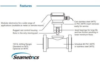
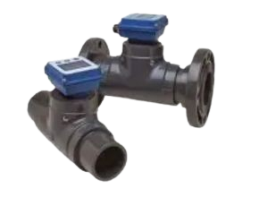
This unique system of 2″ to 8″ turbine flow meter uses just one moving part, a precision helical rotor. Rotation of the rotor is electronically detected and processed. The high-quality jewel bearings and polished zirconia ceramic shafts minimize friction while providing long wear life in non-lubricating fluids. The entire rotor assembly can be easily removed for field service without removing the meter from the pipe.
WTP bodies are fabricated from Schedule 80 PVC fittings, WTC bodies from carbon steel tubing, and WTS bodies (available as special order) from stainless steel tubing. The turbine insert on WTC and WTS meters are machined from a stainless steel casting. The WTP turbine insert is machined from a solid piece of PVC (polypro in 2” size). Turbine rotors on all models are Kynar (PVDF).
WT flow meters can be ordered with various output options. The basic model (100) comes with pulse output only. An electronic display (Seametrics FT420) is mounted on the 101 models to display flow rate and total (resettable or non-resettable) and provide a programmable pulse or 4-20 mA output.
Other electronics options include a blind 4-20 mA transmitter (AO55) on the 102 model and a battery-powered (FT415) rate/totalizer plus pulse output for applications that lack power (104 models). All of these controls/displays can be mounted on the meter or remotely mounted on a wall or panel up to 2,000 feet away. WT-Series flow meters are compatible for use with most other remote-mount Seametrics displays and controls as well.
Features
- One moving part
- Low friction jewel bearings
- Field repairable without removal from the line
- Choice of materials for chemical compatibility
- Variety of displays and control
Applications
- Water treatment
- Wastewater treatment
- Cooling water monitoring
- Industrial fluid control
Turbine Flow Meter Model :
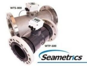
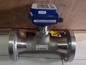
1. WTS Turbine Flow Meter ( Stainless Steel Turbine Flow Meter )
- Stainless-steel body turbine flow meter
- In-line, individually-calibrated turbine meter maximizes accuracy
- The turbine rotor is the only moving part, optimizing low-flow performance
- Solid-state pickup
- The electronic register can be meter-mounted or remote
- Available with blind pulse or 4-20 mA output
- Lightweight, corrosion-resistant 304SS (or optional 316SS) body
- Flanges standard 3″ and above (2″ has female NPT threads)
Specification
- Pipe Sizes : 3”, 4”, 6”, 8”
- Materials
- Meter Body : 304 Stainless steel (316 SS optional)
- Turbine Insert :CF8 cast stainless
- Rotor : Kynar® (PVDF)
- Shaft : Zirconia ceramic
- Bearings Sapphire journal, ruby endstone
- Cable #22 AWG, 2000’ max
- Flanges Optional : . drilling
- Maximum Pressure 200 psi (14 bar)
- Maximum Temperature : 200° F (93° C)
- Accuracy ± 1% of full scale
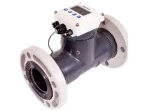
2. WTP Turbine Flow Meter ( PVC Turbine Flow Meter )
- PVC-body turbine flow meter
- In-line, individually-calibrated turbine flow meter maximizes accuracy
- The turbine rotor is the only moving part, optimizing low-flow performance
- Solid-state pickup
- The electronic register can be meter-mounted or remote
- Available with blind pulse or 4-20 mA output
- Materials are chemical-resistant
- Can be ordered with stub ends (standard) or flanges (optional)
Specification
- Pipe Sizes : 3”, 4”, 6”
- Materials
- Meter Body PVC Schedule 80 fittings
- Turbine Insert PVC
- Rotor Kynar® (PVDF)
- Shaft Zirconia ceramic
- Bearings Sapphire journal, ruby endstone
- Cable #22 AWG, 2000’ max #
- Flanges Optional (See dimensions) 150 lb.
- Maximum Pressure 150 psi @ 75° F) n(10 bar @ 24° C) (See chart)
- Maximum Temperature 120° F (50° C) (See chart)
- Accuracy ± 1% of full scale
3. WTC Turbine Flow Meter ( Carbon Steel Turbine Flow Meter )
- In-line, individually-calibrated turbine flow meter maximizes accuracy
- The turbine rotor is the only moving part, optimizing low-flow performance
- Solid-state pickup
- The electronic register can be meter-mounted or remote
- Available with blind pulse or 4-20 mA output
- Heavy-duty, fabricated steel body with topcoat
- Flanges standard 3″ and above (2″ has female NPT threads)

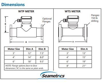
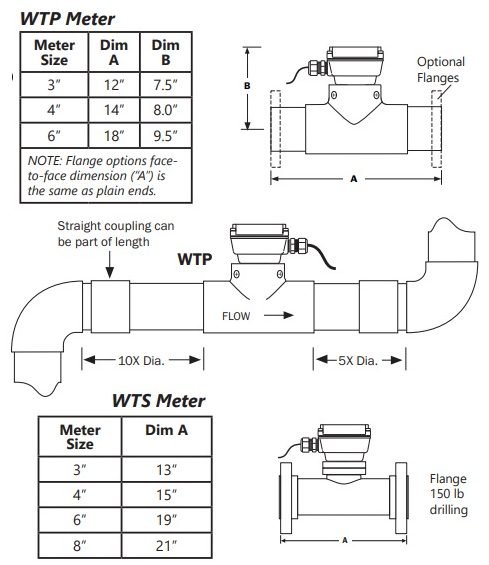
Dimension
Installation and Connection
These water meters are not recommended for installation downstream of the boiler feedwater pump where installation fault may expose the meter to boiler pressure and temperature. Maximum recommended temperature is 120? (PVC) or 200? (Metal).
Piping Conditions.
Installing the meter with 10 diameters of straight pipe upstream and 5 downstream is recommended.
Flanges.
For WTS meters, standard flanges are 150 lb. ANSI drilling. PVC meters can be installed with optional flanges according to pipe manufacturer’s recommendations. For PVC a bolt torque of 20-30 ft-lb for 3” and 4” flanges, and 35-50 ft-lb for 6” flanges is recommended. Either partial or full-face gaskets can be used. Tighten the bolts evenly. Use care to prevent a misaligned gasket from entering the flow stream.
Position.
The WT-Series are all-position meters, operable in a vertical or horizontal position, with the meter insert in any radial position. A horizontal position is preferred if there is a risk of air becoming trapped due to constant low flows. Operating the meter in partially-filled pipe will result in inaccuracies.
Read Another Article :
- Flowma Flowmasonic WUF 620 J Portable Ultrasonic Flow Meter
- Ultrasonic Flow Meter : Prinsip Kerja, Jenis, dan Kelebihannya
- Flowma Flowmasonic WUF 620 CF Clamp On Ultrasonic Flow Meter
- Cara Instalasi Flow Meter Ultrasonic Clamp-on Flowmasonic WUF 500
- Flow meter Air Jenis Ultrasonic clamp on Flowmasonic WUF 500
- Water flow sensor jenis clamp on ultrasonic flow meter
- Flowma Flowmasonic WUF 620 J Portable Ultrasonic Flow Meter
- Flow meter ultrasonic clamp on untuk pipa HDPE
- Flow Meter Ultrasonic Jenis Clamp On Untuk Pipa PVC
- Flow Meter Ultrasonic Clamp on untuk Proses Destilasi Air Laut