
Description
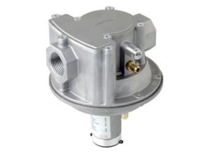
The RAG-type products are pressure regulators for gaseous media, suitable for all types of gas-consuming appliances. RAG is air/gas ratio control (1:1) for combustion processes. It is provided with an adjustable offset spring (+/-3mbar) and adjustable bypass. It is also usable as a zero-pressure governor. All models are equipped with compensation diaphragm to assure high accuracy and are designed to perform lock-up functions.
The RAG-type regulator has the scope of maintaining a constant air-gas ratio upstream of gas burners on installation without preheated air. It is equipped with a bypass adjustable on-site and can be used as a zero-pressure regulator. Elettromeccanica DELTA, with its brands Elektrogas and Deltapumps, is a proud manufacturer of safety and control products for gas firing systems and fuel oil appliances, successfully installed in more than 60 countries in the world.
Features
- The regulators are made of aluminum alloy die-cast, with a range for inlet/outlet connections from 1/2” up to 2”.
- Gas inlet pressure up to 500 mbar, air control pressure up to 120 mbar.
- They are equipped with an adjustable spring and a counterspring, so that gas outlet pressure is equal to air control pressure, with a ratio of 1:1 and an adjustable offset of +/-3mbar. The offset is useful to set gas flow at low fire.
- RAG regulators have been designed for a flow regulation range equal to 10:1 and to generate low-pressure drop.
- The disc is equipped with a gasket, so RAG can regulate precisely very low flow.
- Every model is equipped with a bypass adjustable on-site. Bypass is useful in a low fire state when a very low flow is necessary or air control pressure is lower than 0.5mbar.
- The controls are equipped with an inlet pressure compensation diaphragm for precise regulation.
- A metallic mesh filter protects the regulator seat from dirt contamination (filtration grade <1mm).
- The impulse line is integrated into the regulator. Special versions with external impulse lines are available on request.
- Pipe connections meet group 2.
- Suitable for use with non-aggressive gases included in the 1, 2, and 3 families (EN 437). Special versions for aggressive gases (e.g. biogas).
- Provided with pressure test points in the gas inlet, gas outlet,t, and air control chamber to connect manometers, pressure switches or other equipment.
- RAG can be used as a zero-pressure regulator. In this case, it is necessary to connect the vent port to a discharge pipe or to install the conversion kit
- All components are designed to withstand any mechanical, chemical, and thermal conditions occurring during typical service. Effective impregnation and surface treatments have been used to improve mechanical sturdiness, sealing, and resistance to corrosion of the components.

RAG Electrogas ratio controllerValve
Functioning and application
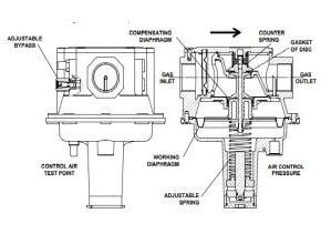
A ratio regulator is a device able to maintain a gas outlet pressure equal to the air control pressure. Outlet gas and control air pressure act on the two sides of the same diaphragm, hence the disc moves until outlet pressure is the same as air pressure. If outlet pressure is
needed to be a bit lower or higher than air, the spring must be adjusted. I
f a gas flow is required to be present when air control pressure is near zero, the bypass must be set. Variation of inlet pressure does not affect outlet pressure because the disc is compensated with a specific diaphragm.
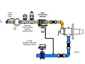
In the case of using the control as a zero-pressure regulator, it is necessary to connect the vent port to a discharge line or screw the optional kit. This device is usually installed in gas-firing systems. The figure below shows an example of installation in combination with other Elektrogas devices.
Technical specifications
- Main connections
- Gas threaded f/f ISO 7-1 from Rp1/2 to Rp2 or ANSI-ASME B1.20 from 3/4”NPT to 2”NPT
Flanged ISO 7005 PN16 from DN25, DN40 and DN50
- Gas threaded f/f ISO 7-1 from Rp1/2 to Rp2 or ANSI-ASME B1.20 from 3/4”NPT to 2”NPT
- Air connection
- G1/4” for models with Rp main threads or ISO flanges 1/4” NPT for models with NPT main threads
- Pressure test points
- Nipples with internal screws and a diameter of 9 mm
- Plugs with threads G1/8” (models with Rp main threads or ISO flanges) or 1/8” NPT (models with NPT main threads)
- Ambient temperature
- -15°C … +60°C
- Gas Inlet pressure P1
- Max 500 mbar (50 kPa) or P out + 2.5 mbar for gas
- Differential pressure between inlet and outlet pressure of less than 100 mbar is advisable.
- Air control pressure P3
- 0.5-120 mbar
- Gas inlet pressure has to be always higher than air control pressure
- Gas Outlet pressure P2
- Air control pressure +/- 3 mbar (adjustable offset)
- Accuracy
- ±1mbar or ±15% of air control pressure (plus offset)
- Max testing pressure Max 750 mbar at inlet chamber – max 200 mbar at air control Chamber
- Flow capacity See charts.
- Bypass flow can be set from 0 to max flow (fig.7)
- Filtration grade with metallic filter <1mm
- Installation
- 1/2”-1”: horizontal (with adjustable spring downwards) or vertical pipeline.
- 1”½-2”: only horizontal (with adjustable spring downwards)
- Gas type
- Natural gas, town gas, LPG (gaseous) of families 1,2,3 (EN437). (for biogas see next page).
- Materials in contact with gas
- Aluminum alloy, Brass, Stainless steel, plated steel
- Polyamide, Anaerobic adhesive, Nitrile rubber (NBR)
- Specifications of J version for biogas or COG
- Free of brass.
- Seals made of Fluoroelastomer (FPM). Without bypass.
Selection
- To select a regulator, it is necessary to know:
- Gas type (natural gas, LPG,…)
- Inlet gas pressure
- Air control pressure (high fire)
- Gas flowrate requested (high fire)
- The regulator will work properly if:
- gas flowrate requested is lower than the max flow rate that the regulator can give with available pressure drop and a suitable margin (advisable +40% for air pressure higher than 40mbar and +80% for air pressure lower than 20mbar) ;
- gas flow rate requested is higher than the minimum flow rate of the regulator. The minimum flowrate is lower than 1/10 of the max flow rate.
- Example:
- Select a ratio regulator:
- for Natural Gas
- gas inlet pressure 80mbar
- max air pressure 20mbar
- requested gas flow 45 Nm3/h
- Select a ratio regulator:
- Considering that outlet gas pressure is equal to air pressure, the available pressure drop is: 80 – 20 = 60mbar
- In fig. 4 we can see the max flow rate with available pressure drop Dp 60mbar (yellow line) and
Natural gas. We consider only regulators with a flow rate higher than that requested (blue line).
For More Information and Price: Delta-Elektrogas RAG Gas Ratio Regulators
Read more articles :
- Wago Sensor/Actuator Boxes
- WAGO TOPJOB S Rail-Mount Terminal Blocks
- Wago High-Tech for Industry and Buildings
- Delta-Elektrogas R-125 Series Medium Pressure Regulators
- Delta-Elektrogas PCS Position Indicator Switch