
General Information
EGE Elektronik Inductive Proximity Switches offer special inductive proximity switches for special applications. The focus is on TROPICAL switches that exceed IP 69K with a temperature range of up to +120 °C and are optimally suited for corrosive environments.
High temperature switches up to 160 °C are also offered. Other hot area sensors can be used in temperatures up to 250 °C. The lower end of the temperature scale is at -60 °C and applies to the POLAR switches. Large switching distances up to 170 mm and sensors resistant to rolling oils made from PTFE, PP or PEEK are also available for the food industry. Intrinsically safe ex-classified sensors according to ATEX and compact dust-EX and gas-EX sensors complete the product program.
EGE Elektronik Inductive Proximity Switches Application
Metal Face Sensors
The inductive proximity switches series IGV are used in areas with heavy-duty mechanical loads at the sensor´s face or where seals between the face and housing cannot be used. Chips hitting the front or frequently changing coolants or lubricants do not diminish the function of these proximity switches.
The variants with a PTFE coating are particularly well-suited for welding lines and similar environments where sensors are exposed to heavy soiling. Metal face switches are manufactured from stainless steel and are one solid piece. They detect iron and steel through the metal front face.
POLAR-Switches
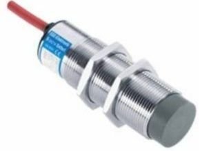
The POLAR switch is ideal for application in cold storage houses and in extreme climate conditions. It is waterproof, safe for cleaning, and extremely chemical-resistant. Because of its stainless steel housing, it can withstand vibrations on vehicles. The POLAR switch is very compact and robust, it can be used from –60 °C to +60 °C.
TROPICAL-Switches
The TROPICAL switches series IGMF are anticipated for applications in corrosive environments. They are stable, particularly at frequent temperature changes and simultaneously high humidity. The permanent work in carwashes is permissible. The high corrosion resistance at simultaneously high mechanical loading capacity is reached through the combination of PTFE and titan-stabilized stainless steel.
The PTFE-hoods are sealed through fluoroelastomers O-rings surely. The FEP-connecting cable is poured within the housing and freed over a double seal from the housing. Cable lengths up to 100 m are available. The installed LEDs are shining through the cable side cap and don’t break out of the case.
120 °C-High temperature switches
The inductive PTFE switches series IGFW and INFW are made entirely of PTFE. The housing cover is securely sealed with a fluoroelastomer O-ring. These sensors are designed for particularly difficult and aggressive environmental conditions. They can be used in damp and aggressive environments as well as underwater (oil).
IGMT- and IDT-series proximity switches are designed for use in temperatures up to 120 °C.
160 °C-High temperature switches
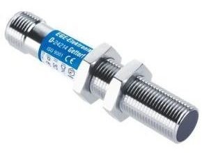
Inductive compact devices for ambient temperatures up to 160 °C are available flush and non-flush in the standard designs M12, M18, and M30 with switching distances from 2 mm to 15 mm. The material used is the rugged stainless steel housing combined with high temperature-resistant PEEK plastic.
250 °C-High temperature switches
The inductive proximity switches series IGH/IDH/IRH are used for ambient temperatures up to 250 °C. The units feature an optional plug connection that withstands high temperatures, allowing users to quickly and easily install a replacement sensor head in case of damage without having to replace the sensor cable.
The sensors are particularly suited for operation in extreme heat, e. g. in drying ovens or brick kilns. Manufactured from aluminum / stainless steel and PEEK, the robust sensors can be used in rugged industrial environments. Their electronics are housed separately in a pluggable cable amplifier. The units are connected via a metal armored cable.
Amplifiers
Switching amplifiers are designed for induction sensors for which it is necessary to separate the sensor coil from the amplifier, e. g. for operating temperatures above 160 ºC or for sensor coils that must be exchanged due to frequent damage. The switching amplifiers work statically, that is, if the sensor coil is permanently damped, the switching output also remains activated. Switching interval and hysteresis (IKM 120 GPP, IU 130…) can be set on the amplifier. The sensor cable may have a length of up to 20 m.
Demanding environment
The “Demanding environment” series is specially designed for harsh environments in which sensors are subjected to high electrical, electromagnetic, or mechanical stress. For sensors used in critical applications, EGE has developed special inspection and test methods that place particular emphasis on the disturbances that occur in various production environments. The sensors are designed to be very resistant to the interference spectra produced by, e.g., frequency inverters, wireless communication systems, and switching power supplies.
Surface Sensors IFE
The switches are built as flat sensors. They are used particularly to detect moving sheet metal or steel rods on conveyor belts. The complete sensor is covered, which makes the sensor moisture-resistant. Reduced overall height affects the operating distance (sn). The IFE switches are self-contained with an integral amplifier.
Dust-and Gas-Ex sensors
IGEX and IGVEX are sensors for detecting metals in the Ex area zone 0/20 and zone 22 according to ATEX and IECEx. Devices can be delivered in the standard configurations M12, M18, and M30. For extreme environments sensors are available for high and low temperatures (up to +140 °C and down to –60 °C respectively), both in IP 68 / IP 69K.
More Articles: Ege Elektronik Flow Sensor and Flow Measurement
EGE Elektronik Inductive Proximity Switches – Installation
Mounting
For flush mounting, the sensor can be built into metal up to its active surface without changing its characteristics. For non-flush mounting, a metal-free zone around the sensor must be allowed. A free zone to the material opposite the sensor must be maintained for all sensors.
Variable mounting of the sensors is possible by our assembly aids.
Collocation
When collocating the sensors, a minimum separation must be kept between the devices in order to avoid mutual influence. When in doubt, a test should be conducted under application conditions.
For flush mounting, the lateral separation between two sensors must correspond to at least the diameter of the sensor. For non-flush mounting, the lateral separation from one another must correspond to at least twice the diameter of the sensor. For separations greater than eight times the diameter, no mutual influence is to be expected. For oppositely mounted sensors, a minimal separation of eight times the nominal switching separation should be allowed.
Torques
To prevent the destruction of the threaded bushing during fitting, the following maximum torques must not be exceeded:
Instructions for operation
Serial connection
For the serial connection of two-wire or three-wire sensors, the individual voltage drops are added together. Therefore there is a lesser operational voltage at the disposal of the load. The addition of the switch-on delay times should be noted.
Parallel connection
The parallel connection of two-wire sensors can only be conditionally recommended since the residual currents are added together and flow through the load. For the parallel connection of three-wire sensors, the current consumption of the individual devices is added together. Since this current does not flow through the load, the maximum number of parallel connectable three-wire sensors depends only on the power supply.
Approval for safety applications
Sensors for personal security must have a qualification approval according to EN 954-1 and must be labeled accordingly. Sensors that are not labeled must not be used for applications of this kind.
EGE Elektronik Inductive proximity switches – Terminology
Operating Principal
An inductive proximity switch works with a high-frequency oscillating circuit that creates an alternating electromagnetic field on the active sensor surface using a coil. When a metallic object nears this field a damping occurs in the oscillating circuit. If this damping exceeds a threshold value, a switching signal is generated.
Operating distance
The operating distance is the distance between an object and the active sensor surface at which a switching signal is generated. The operating distance depends on the diameter of the coil. Therefore larger sensors are required for longer operating distances. On some of the EGE sensors, the operating distance is adjustable. If a metal object dampens only a part of the alternating field, the operating distance decreases; a larger object increases it.
The following approximate values are derived from a standard rectangular measurement plate made of steel ST 37 with an edge length that corresponds to the diameter of the sensor coil or three times the rated operating distance, whichever is greater.
The operating distance is influenced by the material of the object: Constant dimensions for different materials against steel ST 37 yield a changed operating distance. The following table lists approximate values for the material-dependent reduction factors. In practical applications, variations could occur due to different alloying, for example.
Rated operating distance sn
The rated operating distance is a device parameter that does not take into account sample variances and external influences such as temperature and supply voltages.
Effective operating distance sr
The effective operating distance is the operating distance at a nominal voltage and a nominal temperature of 23°C. It is between 90 % and 110 % of the rated operating distance.
Usable operating distance su
The usable operating distance lies in the entire allowable temperature and voltage range between 90 % and 110 % of the effective operating distance.
Assured operating distance sa
The assured operating distance takes into account all the external influences and sample variances and lies in the range from 0 % to 80 % of the usable operating distance. Within this range, a guaranteed switching is ensured.
Switch point drift
The operating distances are given for an ambient temperature of 23°C. In the permissible temperature range, the operating distance varies by less than 15 % from the value at 23°C. The temperature of the measured object does not influence the switch point.
Hysteresis H
The switching hysteresis describes the distance between the turn-on point while approaching an object and the turn-off point during the separation of it from the sensor. The hysteresis brings about a stable switching signal even when there are vibrations, temperature drift, or electrical variations. The hysteresis is defined in EN60947-5-2 as a maximum of 20 % from the effective operating distance and carries a value of typically 10 % from the effective operating distance sr for EGE sensors.
Repeating Accuracy R
The repeating accuracy describes the maintenance of the switching point after the repeated approach of an object under specified circumstances. EGE sensors have typical tolerances of less than 3 % of the effective operating distance.
Switching frequency
The maximum switching frequency of the sensor is determined at half-rated operating distance sn with standard measurement plates to EN 60947-5-2
Operating voltage
The operating voltage is the voltage range within EGE sensors to function safely. For a constant voltage supply, it is important to make sure that the limits are still observed when the residual ripple is included.
Current carrying capacity
This current gives the maximum long-term current for the switching output of the sensor at an ambient temperature of 25 °C and ohmic load. At an elevated ambient temperature, the current load capability decreases. For analog outputs, the boundary values given in the appropriate technical data, particularly the permissible values for resistance loads, must be observed.
Short circuit protection
The short circuit protection ensures the sensor against destruction through a short circuit on the output. After the removal of the fault, the output is reactivated. Where a maximum overload current is listed, this should not be exceeded.
Excess-current release
This value indicates the median value of the current at which the short circuit protection responds with a tolerance of ± 20 %.
Reverse polarity protection
The reverse polarity protection prevents the destruction of the sensor by a reversal of the polarity of the voltage supply.
Voltage drop Ud
The voltage drop arises at the internal resistance of semiconductor elements, which are in the current path of the output. It is dependent on the load current and is declared for a mean current of 200 mA.
Residual current Ir
The residual current flows in the load current circuit when the output is blocked. The residual current must be considered when switching sensors in parallel.
Minimum load current Im
The minimum load current is necessary for flawless operation with two-wire devices.
Current consumption
The current consumption is the maximum value of the no-load current Io that the sensor can absorb without a load.
Ambient temperature
The ambient temperature indicates the maximum allowable temperature range for the sensor.
Electromagnetic compatibility EMC
The EMC class is a measure of the noise immunity of the sensor against external electrical and magnetic influences. The information is based on the standard EN 61000-6-2.
Switch-on impulse suppression
EGE sensors have a switch-on impulse suppression that blocks the output during the switch-on phase when the operational voltage is applied.
Protective system
The protective system indicates the protection of the sensors against penetration of foreign bodies and water to EN 60529.
LED-display
EGE Elektronik Inductive Proximity Switches with yellow light-emitting diodes indicate the switching status optically.
Housing material
The housing material determines the chemical resistance of the sensor against external influences. For special applications, other housing materials are available.
Connection
The connection of the sensors is accomplished through plugin connections or cables. Different cable types and lengths are available upon request.
More Articles: Ege Elektronik special purpose sensors for automation
Another Article:
- Omron M30 E2B Proximity Sensor
- Omron M18 E2B Proximity Sensor
- Deep Sea Electronics DSEE400
- Omron E2EY Alumunium Detecting Proximity Sensor
- Nivelco Microwave Radar Level Measurement
- Nivelco Level Switch
- Nivelco Industrial Sensor Process Control