
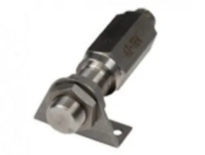
Description
Magnetic Hall Effect Sensor BH Series, available from AI-Tek, are Bi-directional, zero velocity sensors are self-calibrating to the specific customer application and provide two independent frequency outputs and a direction signal output to indicate a change in direction of the sensed, ferrous target.
The Magnetic Hall Effect Sensor BH Series bi-directional sensor can also be referred to as a dual-channel sensor since it utilizes two Hall effect sensing elements that physically offset from each other. Each element generates a single channel of target information, identical in frequency and polarity, but offset in the time domain (phase shifted).
Special circuits inside the sensor are designed to calibrate each channel to its application target, then analyze these two channels of information for a phase lead/lag condition. The direction output will then provide a logic 1 level for clockwise or a logic 0 for counterclockwise rotation, assuming proper sensor orientation.
For applications with cable runs that exceed 500 feet, you will need to use a Digital Signal Distance Amplifier (DSDA). AI-Tek Bi-directional, zero velocity sensors are self-calibrating to the specific customer application and provide two independent frequency outputs and a direction signal output to indicate a change in direction of the sensed, ferrous target.
The Bi-directional sensor can also be referred to as a dual-channel sensor since it utilizes two Hall effect sensing elements, physically offset from each other. Each element generates a single channel of target information, identical in frequency and polarity, but offset in the time domain (phase shifted).
Special circuits inside the sensor are designed to calibrate each channel to its application target, then analyze these two channels of information for a phase lead/lag condition. The direction output will then provide a logic 1 level for clockwise or a logic 0 for counterclockwise rotation, assuming proper sensor orientation.
Features
- High-temperature range of -40°C to +125°C
- Supply Tracking or TTL Compatible output options
- Power on calibration
- Requires special alignment
- Controlled duty cycle
- Fine pitch performance
- Increased air gaps
- Wide range of supply voltage in single design of 10 – 28 Vdc
- Special circuitry provides high level of EMI hardness
- Reverse voltage protection, up to -30 Vdc, to prevent damage if miswired
- Rugged sensors designed to meet the toughest Navy ship-board standards to European Railroad Applications
Specification
| Power Supply | |
| Power Supply Voltage | 10 – 28 Vdc |
| Power Supply Current | 100 mA maximum |
| Outputs | |
| Output Voltage | Essentially square wave fanout to 10 TTL inputs |
| TTL Compatible | 40% to 60% duty cycle |
| Logic 0: +.6 Vdc maximum | |
| Logic 1: +4 to +5.0 Vdc @ 5mA | |
| Supply Tracking | 40% to 60% duty cycle |
| Logic 0: +.6 Vdc maximum | |
| Reverse Battery Voltage | -30 Vdc |
| Environmental | |
| Operating Temperature | -40°C to +125°C |
| Thermal Shock | 100 cycles air to air (-40° to +130°C) |
| 1 min. ramp time with 30 min. soak | |
| Salt Spray | Per MIL-STD-202, method 201, test cond. B, 5% NaCl for 48 hrs. No visible corrosion |
| Humidity | 92% RH@ 40°C for 90 hrs. No visible corrosion. |
| Dielectric Strength | Per MIL-STD-202, method 301, 1000 Vrms (60Hz) for 5 sec. leads to the case. 1.0 mA max. leakage |
| Insulation Resistance | Per MIL-STD-202, method 302, 500 Vdc for 30 sec. leads to the case. 100 mega-ohm min. |
| Vibration | Per MIL-STD-202, resonant frequency search, sine method 204, test cond. C&D (20g); random method 214a, test cond. A&B (7.56g) for 15 min. |
Download Data Sheet: Magnetic Hall Effect Sensor BH Series
Ref: aitekinstruments.com
Other Article:
- GF Signet Flow Sensor
- Capacitive Proximity Sensors
- Photoelectric Proximity Sensors
- Isoil Sensor for Flow Meter
- Sika Sensors and Measuring Instruments