
DESCRIPTION
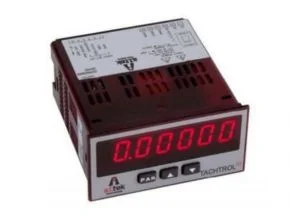
AI- Tek 20 Series Tachometers Tachtrol is the newest member of the AI-TEK Tachometer family. It is a single input digital instrument designed to provide the versatility and flexibility needed to accommodate virtually any rate measuring application.
The Tachometers Tachtrol 20 Series, Model T77250-10, provides the versatility and flexibility needed to accommodate virtually any rate measuring application. The meter has the ability to scale for direct readout in terms of the units being measured.
Whether a machine produces bottles, cloth, wire, or beverage mix, the operation is enhanced when the rate readout is expressed directly in bottles/min., feet/min., gallons/min., or whatever units are needed in-plant applications. The Tachometers Tachtrol 20 Series can accommodate magnetic pickups, logic sensors, and NPN open collector sensors. The pulses are received and scaled, so the desired display can be achieved.
The Tachometers Tachtrol 20 Series is programmed through both the front panel buttons and DIP switches. Once the programming is complete, the front panel buttons can be disabled by a DIP switch setting. The Tachometers Tachtrol 20 Series has been specifically designed for harsh industrial environments. With a NEMA 4X/IP65 sealed bezel and extensive testing to meet CE requirements, the meter provides a tough, yet reliable application solution.
All safety-related regulations, local codes, and instructions that appear in the literature or on equipment must be observed to ensure personal safety and to prevent damage to either the instrument or equipment connected to it. If the equipment is used in a manner not specified by the manufacturer, the protection provided by the equipment may be impaired.
The Tachometers Tachtrol 20 Series meets NEMA 4X/IP65 requirements when properly installed. The unit is intended to be mounted into an enclosed panel. Prepare the panel cutout to the dimensions shown below. Remove the panel latch from the unit.
Slide the panel gasket over the rear of the unit to the back of the bezel. The unit should be installed fully assembled. Insert the unit into the panel cutout. While holding the unit in place against the panel, push the panel latch over the rear of the unit so that the tabs of the panel latch engage in the slots on the case. The panel latch should be engaged in the farthest forward slot possible. To achieve a proper seal, tighten the latch screws evenly until the unit is snug in the panel (Torque to approximately 7 in-lbs [79N-cm]). Do not over-tighten the screws.
AI- Tek 20 Series Features
- Single-channel precision speed or rate monitoring
- Field adjustable scaling
- Bright six-digit LED display
- Wide frequency range 0.1 to 25 kHz
- Active or passive sensor input
- Panel Mount 1/8 DIN standard housing
AI- Tek 20 Series Specification
| Display | 6-digit, 0.56″ (14.2 mm), 7-segment red LED. Decimal points are programmed by front panel keys. |
| Power | |
| AC Power | 115/230 VAC, switch selectable. Allowable power line variation ±10%, 50/60 Hz, 6 VA. @ 100 mA max. |
| Isolation | 2300 Vrms for 1 min. to input and DC Out/In. |
| DC Power | 10 to 16 VDC @ 100mA max |
| Sensor Power | 9 to 17.5 VDC @ 100mA max. |
| Keypad | 3 programming keys, the ? (Down Arrow) key can also function as the front panel reset button. |
| Input | (DIP switch selectable) |
| Accepts pulses from a variety of sources including NPN-OC, PNP-OC, TTL Outputs, and Magnetic Pickups. | |
| Logic | Input trigger levels V il, = 1.5 V max.; V ih, = 3.75 V min. |
| Current Sinking | Internal 7.8 K? pull-up to +12 VDC, I max = 1.9 mA |
| Current Sourcing | Internal 3.9 K? pull-downs, 8 mA max. @30 VDC max. |
| Magnetic Pick-Up | |
| Sensitivity | 200 mV peak |
| Hysteresis | 100 mV |
| Input impedance | 3.9K? @ 60 Hz |
| Maximum input voltage | 40 V pk-pk, 30 Vrms |
| Input Frequency Range | |
| Max Frequency | 25 KHz |
| Min Frequency | 0.01 Hz |
| Accuracy | ±0.01% |
| Memory | Nonvolatile EEPROM retains all programmable parameters and display values. |
| Environmental Conditions | |
| Operating Temperature | 0° to 60°C |
| Storage Temperature | -40° to 60°C |
| Operating and Storage Humidity | 0 to 85% max. relative humidity (non-condensing) |
INSTALLING THE METER
The TACHTROL20 meets NEMA 4X/IP65 requirements when properly installed. The unit is intended to be mounted into an enclosed panel. Prepare the panel cutout to the dimensions shown below. Remove the panel latch from the unit. Slide the panel gasket over the rear of the unit to the back of the bezel. The unit should be installed fully assembled. Insert the unit into the panel cutout.
SETTING THE SWITCHES
The meter has DIP switches that must be checked and/or changed prior to applying power. To access the power switch, remove the meter base from the case by firmly squeezing and pulling back on the side rear finger tabs. This should lower the latch below the case slot (which is located just in front of the finger tabs). It is recommended to release the latch on one side, then start the other side latch
While holding the unit in place against the panel, push the panel latch over the rear of the unit so that the tabs of the panel latch engage in the slots on the case. The panel latch should be engaged in the farthest forward slot possible. To achieve a proper seal, tighten the latch screws evenly until the unit is snug in the panel (Torque to approximately 7 in-lbs [79N-cm]). Do not over-tighten the screws.
Download Data Sheet: Tachometers Tachtrol 20 Series
Ref: geniefilter.com
Another Article:
- A.I Tek Instruments Tachometer Transducer
- A.I Tek Instruments Accessories Digital Signal Distance Amplifier
- A.I. Tek Instruments Tachometers Tachpak 30 Series
- A.I. Tek Instruments Passive Speed Sensors Series 70082 – Side Lock
- AI- Tek Tachtrol 30 Series Tachometers
- AI- Tek 20 Series Tachometers Tachtrol
- AI- Tek Instruments Tachometers Tachtrol 10 Series
- AI- Tek Instruments Accessories Digital Signal Distance Amplifier
- AI- Tek Tachometer Transducers