
Description
Eaton Bypass Isolation Contactor transfer switch is used in life safety and other mission-critical applications where redundancy is desired and maintenance of the automatic transfer switch can be performed without interrupting power to the load. Transfer switches can be equipped with the ATC- 300+ or ATC-900 controller.
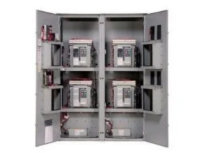
Eaton Bypass Isolation Contactor Configuration
- 100, 150, 200, 225, 260, 400, 600, 800, 1000, 1200 and 1600 A
- Two-, three- or four-pole (the fourth pole is fully rated)
- Up to 600 Vac, 50/60 Hz
- NEMA 1, 3R, 12, 4X
Design Highlights
- Front access is a standard feature on all ratings
- Entry:
- Top, bottom or both
- Isolated compartments
- Improved safety:
- Isolated compartments with barriers
- Single motion rack-out with doors closed
- Ability to test power switching elements during drawn out process
- Dual ATS capability—both the ATS switch and bypass switch operate in automatic mode
- Installation flexibility:
- Field entry/exit locations can be modified in the field
- Interchangeable draw out contactors
- Field-selectable multi-tap transformer panel permits operation on a wide range of system voltages
- Dual draw out—ATS and bypass
Eaton Bypass Isolation Contactor Features, Benefits, and Functions
Standard Features
- Drawout cassette design on both ATS and bypass
- No service interruption in bypass to the same source
- Source available contacts:
- Source 1 present
- Field-programmable time delays:
- Time delay engine start: 0–1200 seconds
- Time delay normal to an emergency.
Optional Features
- Surge protection(UL 1449 3rd Edition)
- Eaton IQ and Power Xpert multi-function power quality metering
- Automatic transfer mode 2NO and 2NC 0–1800 seconds
- Source 2 present 2NO and 2NC
- Switch position contacts:
- Source 1 position 1NO and 1NC
- Source 2 position 1NO and 1NC
- Source 1 and Source 2 senses:
- Undervoltage/ under frequency
- Overvoltage/ over frequency
- Three-phase rotation protection (ATC-300+ only)
- Three-phase voltage unbalance/loss (ATC-300+ only)
- Pretransfer signal contacts 1NO and 1NC (open transition only)
- Go to Source 2 (EMERGENCY)
- Time delay emergency to normal: 0–1800 seconds
- Time delay engine cooldown: 0–1800 seconds
- Time delay emergency failure: 0–6 seconds
- LCD-based display for programming, system diagnostics and Help menu display
- Mimic diagram with source available and connected LED indication
- Time-stamped history log
- System TEST pushbutton
- Programmable plant exerciser—OFF, daily, 7-, 14-, 28-day interval selectable run time 0–600 minutes no-load/ load with fail-safe automatic/automatic retransfer mode
- Modbus RTU via RS-485
- Remote annunciation with control
- Open in-phase transition, time delay neutral or in- phase with a default to time delay neutral transfer
- ATC-900 controller
- Includes Modbus RTU via RS-485
- Includes four programmable inputs/ outputs
- Includes two plant exercisers
- Includes LCD color display with easy navigation tools to settings and event logs
- Expandable I/O (up to 20 I/O total)
- Optional integrated load metering
- Optional Ethernet TCP/ IP communications
Another Article:
- Sound Velocity of Material
- Eaton Contactor Based ATS Transfer Switch
- Eaton High Torque Hydraulic Motor
- Pengertian dan Jenis Relief Control Valve
- Bamo GNR 4 Bypass Level Indicator GNR 4
- Kelco Engineering E30-MK2 Digital Pressure Switch
- Transmitter CP 114 – CP 115 – Differential pressure sensor
- Camsco TB-35 24 Hours Automatic Time Switch
- Nason Temperature, Vacum, Pressure and Temperature Switch
- Shunt Trip Safety Switch