
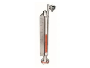
Description
TC Fluid Control Instrument Chambers are used in conjunction with liquid level sensors and are designed to give an uninterrupted level indication of most liquids including steam condensate as well as arduous chemicals. For certain applications, it can also sense an interface level within the chamber.
The Instrument Chamber comprises of a sealed bridle/bypass arrangement in which a variety of different liquid-level sensors can be accommodated. The principle of operation is dependent on the type of sensor fitted inside the chamber. See the sensor I.O.M. for details.
TC Fluid Control Gauges are manufactured in accordance to the requirements as specified in the Pressure Equipment Directive 2014/68/EU (Modules B+D) and where applicable to ATEX mechanical Directive 2014/34/EU.
Design codes used are in accordance to the requirements as specified in ASME B31.3 / ASME B31.1 under Lloyds Register (Notified Body Number 0038) or AD2000 code under TÜV (Notified Body Number 0036). Refer to the Declaration of Conformity supplied for full details.
- Quick Despatch – typically 4 weeks for standard materials & without special testing.
- Design Codes: AD2000 or ASME B31.3
- Construction: Butt welded or slip-on welded flanges
- Pressure rating: Up to Class 2500 PN400
- Size: Diameter Up to 6” (DN150) N.B Pipe
- Length: unlimited – (6m in one section)
- Materials: Carbon Steel, St/Stl, Duplex F51/F53, Monel, Hastelloy, 6Mo, Inconel (others on request)
- Full NDE testing available – Radiograph, Dye Penetrant test, PMI (others on request)
TC Fluid Control Instrument Chambers Function
- Ensure that the instrument chamber is isolated from the vessel.
- Connect sensor as required following the correct electrical procedures (see sensor I.O.M.)
- The level within the chamber can be imitated by pouring water or a suitable media (compatible dielectric constant) into the chamber via the top vent.
- Perform ‘set up’ procedure as per manufacturer instructions. Record and calibrate.
- Open the drain/drain valve and allow the water/suitable media to run out, thus simulating a falling level.
- Check function of any other ancillaries fitted.
- Close vent and drain.
TC Fluid Control Instrument Chambers Specification
Maintenance maintenance is required other than periodic inspection to ensure that the chamber is free from foreign particles, sediment or scale, etc. Removal of the Instrument Chamber.
- Isolate the instrument chamber from the source of pressure/media by closing the appropriate isolation valves.
- Relieve the chamber of any internal pressure and fluid contents by opening the drain valve. Ensure all safety precautions are in place for safe disposal of the contents. Time must be allowed for the chamber and contents to cool prior to this operation.
- Warning: The pressurized instrument chamber may contain potentially hazardous fluids. Wear appropriate protective clothing.
- When the chamber has cooled, isolate and remove any ancillary equipment.
- Dismantle respective vessel connections and remove the chamber.
- If the chamber is to be returned to TC Fluid Control, it is the responsibility of the user to ensure the chamber is cleaned and safe to handle without any special precautions. TC Fluid Control must be contacted prior to return of the chamber and associated sensor (where applicable) TC Fluid Control reserve the right to charge any user for safe disposal if these precautions do not adhere too.
Service Life
Service life depends upon the combination of pressure/temperature and the media. The effects of chemical agents, corrosion and vibration are covered by the requirements of the PED 2014/68/EU. Alternative materials can be supplied for certain arduous conditions.
Generally, service life for the gauge is 5 years unless otherwise specified. It is recommended that the instrument chamber system should be inspected on an annual basis. Inspect for corrosion and wear both internally and externally.
Insulation Jackets
If fitted, TC Fluid Control insulation jackets have a service temperature range from -60°C to +250°C and are fabricated to suit a particular instrument chamber configuration.
Spares
All replacement components must be genuine TC Fluid Control spares. When ordering, the TC Fluid Control job/order number including the tag number should be quoted. This information can be found on the nameplate, which is normally fitted onto the bottom flange.
Transportation
The shipment / transportation of level gauge/s should be kept in a clean dry and sheltered environment and not exposed to any adverse weather conditions.
Storage
The level gauge should be stored indoors in its original packaging in a clean dry and sheltered ventilated area preferably between -40°C to +60°C. All gauges should be visually inspected upon receipt on-site in order to assess if any damage has occurred during shipment/transportation. Any such damage should be reported to TC Fluid Control immediately. It is recommended that the Instrument chamber/s is stored in their original packaging until ready for installation.
Instrument Chambers subjected to ATEX requirements
An instrument chamber is outside the scope of ATEX as there is no “self-source of ignition”. However by fitting an instrument (hazardous area approved) onto the gauge, the configuration then becomes an assembly, therefore considerations must be made for both approved and non-approved parts.
Download Datasheet: TC Fluid Control Instrument Chambers
Reference: tc-fluidcontrol.com
Another Article:
- Magnetic Vertical Level Switches Delta Mobrey
- TC Fluid Magnetic Float Switch (Vertical)
- Hengstler 499 Time Counter
- TC Fluid Sanitary Level Sensor
- Quality Gauge & Valve Series Q20 Liquid Level Gauge
- Delta Mobrey 246781ZA High Pressure Electrode
- APG FS-500 Series Stainless Steel Horizontal Float Switch
- APG IRU-9400 High Sensitivity 35 Ft Ultrasonic Level Sensor
- Quality Gauge & Level Series Q175 and Q170 Tubular
- Aquaread Liquid Leveline
- Process Level Gauges TC Fluid Control