| Current Consumption [mA] | < 200 mA at 12-30 VDC reflective |
| < 250 mA at 12-30 VDC with backlight | |
| <250 mA at 24 VAC | |
| <50 mA at 115, 230 VAC | |
| <80 mA at 100-240 VAC switching power supply | |
| Power Consumption | < 5 W <8 W |
| Cable Cross-Section | 1…1.5 mm² (0.0015…0.0023 in²) with the multicore cable end |
| Input Resistance | approx. 10 kOhm |
| Pulse Length min. | 17 ms (30 Hz), 8 µs (60 kHz) |
| Supply Voltage | 12-30 VDC |
| 24, 115, 230 VAC | |
| 100-240 VAC | |
| Count Frequency [Hz] | max. 60 kHz (TTL 20 kHz): Single-channel counting and directional input |
| max. 60 kHz (TTL 20 kHz): differential or totalizing operation | |
| channel (A+B together) | |
| max. 30 kHz (TTL 20 kHz): phase discriminator 1- or 2-fold evaluation | |
| max. 15 kHz (TTL 15 kHz): phase discriminator 4-fold evaluation | |
| attenuated 30 Hz | |
| For further details, see the graphic and manual. | |
| Overload Protection | ext. backup |
| DC: 0.16 AT (IEC 127), DC: 0.2 AT (UL 198) | |
| 24 VAC: 315 mAT | |
| 115 VAC: 63 mAT | |
| 230 VAC: 32 mAT | |
| 100-240 VAC 630 mAT | |
| Overload Protection Relay Output | ext. backup 230 V |
| 2.5 A mT | |
| Sensor Supply | transformer power supply: 12-24 VDC (load-dependent) |
| max. 50 mA | |
| switch power supply24 VDC -5% | |
| max. 115 mA, max. capacitative load 470 µF | |
| Storage of Values | NVM> 10 years |
| Electrical Connection | pluggable screw terminals / connecting clamps |
| Amplitude Threshold | < 2 V and > 8 V or < 1 V and> 4 V at TTL levels |
| amplitude max. 40 VDC | |
| Active Edge | programmable, positive with PNP input, negative with NPN input |
| Pulse Shape | any square wave (1:1 for max. frequency) |
| Prescaler | 0.0001 – 99.9999 |
| Set Function | set to VW 0 (independent of resets) |
| Display and Preset Range | – 999 999 to + 999 999 |
| Alarm Signal | display blinks |
| when presets 0,1 or 2 are active | |
| Relay (Preset 1 and 2) | Varistor max. 250 VAC / 30 VDC / 5 A |
| Varistor min. 5 VAC / 5 VDC / 10 mA | |
| Delay < 10 ms | |
| Transistor output (Preset 1 + 2) | DC supply: PNP output 12 – 30 VDC, max. 50 mA |
| transformer performance (24, 115, 230 VAC): PNP output 12 – 24 VDC, max. 30 mA | |
| switch power supply 100-240 VAC: PNP output 24 VDC, max. 50 mA | |
| Application Output | DC supply: PNP output 12 – 30 VDC, max. 20 mA |
| transformer performance (24, 115, 230 VAC): PNP output 12 – 24 VDC, max. 20 mA | |
| switch power supply 100-240 VAC: PNP output 24 VDC, max. 20 mA | |
| Attention | Only for transformers (24, 115, m230 VAC: |
| The energy load on the outputs (sensors 12-24 VDC, out1, out2, Appl.-Outp.) may not be more than 65 mA total. |
Counter
| Counter Mode Input A, B | Single-channel add or sub, directional input, |
| differential operation add / sub, totalizing operation add/add, | |
| phase discriminator 1-, 2- or 4-fold evaluation | |
| Preselect Modes | absolute or trailing preset |
| range signal/value limit (Sign. 1 < VW1) | |
| Sign. 2> VW2 | |
| Application Input/Output (Counter) | Output: Prescaler-out |
| preset 0-out | |
| direction-out | |
| input: additional counter input add / sub | |
| reset | |
| set | |
| gate | |
| keylock | |
| hold | |
| teach-in | |
| Mode | batch counter with preset or 2. totalizing counter with preset |
| Count Mode | differential operation add/sub |
| totalizing operation add/add |
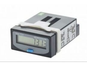
Hengstler Tico Time Counter Tachometer
| Measuring Principle (tachometer) | period measurement (1/tau) |
| Display Range | 1/min or 1/sec |
| min. Frequency | 1 Hz or 0.1 Hz |
| Limit Values | 2 alarms with programmable start suppression |
| + 1 additional upper limit on the application input | |
| Tachometer Mode of Operation | Single-channel add or sub, directional input, |
| differential operation add / sub, totalizing operation add / add, | |
| phase discriminator 1-, 2- or 4-fold evaluation | |
| A / B or (A-B) / A % | |
| Application Input/Output (Tachometer) | Output: preset 0-out |
| direction out | |
| input: additional counter input add / sub | |
| gate | |
| keylock | |
| hold | |
| teach-in | |
| Accuracy of the Tachometer Function | Timebase: ± 30 ppm |
| Measuring principle: cycle duration measurement | |
| Measuring time: min. 0.5s / max. 1s or 10s | |
| Measuring resolution: 0,4 µs (<30 ppm) | |
| Display resolution: 4 decimal points | |
| 1 digit = 100 ppm | |
| Overall Tolerance (Tachometer) | = display resolution + tolerance time base = 130 ppm |
Time Counter
| Time Base (Tachometer) | programmable, sec |
| min | |
| h or hh.mm.ss | |
| Measuring Principle (timer) | pulse width or period duration measurement (start-stop) |
| start Inp. A + Stop Inp. B, | |
| Start/Stop button | |
| Function Time Counter | single pulse measurement or cumulative measurement |
| Application Input/Output (Timer) | Output: preset 0-out |
| input: additional Run | |
| Stop | |
| Reset | |
| Set | |
| Keylock | |
| Teach in | |
| Accuracy of the Timer | Timebase. ± 30 ppm |
| Start / Stop time point: 16 µs / 16 ms (unattenuated/attenuated) | |
| resolution: 100 µs = 100 ppm | |
| Overall Tolerance (Timer) | = display resolution + tolerance time base = 130 ppm |
| Resolution | 1, 0.1, 0.01, 0.001, 0.0001 |
Environment and Security
| IP Protection Class | IP 65 |
| Operating Temperature [°C] | 0 ?… + 50 °C (+ 32 … 122 °F) EN 60 068-2-1/2 |
| Storage Temperature [°C] | – 20 … + 65 °C (- 4 … + 149 °F) EN 60 068-2-1/2 |
| Degree of Protection | IP 65 front, EN 60529 |
| IP 20 connections | |
| Cable Length | An additional protective circuit is required when using cables longer than 30 m |
| which are connected to a DC power supply at TTL input levels | |
| General Design | EN 61 010-1 / IEC 61010-1 |
| EMC – Interference immunity | EN 61326-1 Industrial** |
| EMV-Emission | EN 61326-1 Class B* |
| Approvals | UL |
| CSA File-Nr. E 338588 | |
| Vibration Resistance | 10 m/s² (33 ft/s²) (10 . 150 Hz), EN 60 068-2-6 |
| Shock Resistance | 100 m/s2 (328 ft/s2) (18 ms) acc.IEC 068-2-27 |
| Protection Class | II, EN 61010-1 / IEC 61010-1 |
| Contamination Level | V 2 |
| EN 50178 | |
| Climate | 40°C (104 °F)/ 93% RH class 4K4H |
| EN 60 068-2-78 | |
| 25 – 50°C (122 °C) / 93% RH | |
| cyclic | |
| EN 60 068-2-38 | |
| elevations up to 2000 m (6561 ft) | |
| Resistance to Chemicals | front film acc. DIN 42 115-2 |
| RoHS | compliant |
Mechanical
| Size [mm] | 48x48x118 |
| Mounting Options | Clamping frame |
| Mounting | with clamping frame |
| Reset | manual reset using a keypad |
| external reset static or dynamic | |
| pulse duration min. 5 ms | |
| automatic reset after preset 2 has been reached | |
| no loss of pulse at the maximum counting frequency due to automatic resetting. programmable using application input and power-up reset | |
| Weight [g] | approx. 200 g (3.2 oz) |
| Dimensions [mm] | 48 mm x 48 mm x 118 mm (1.9×1.9×4.6 in), installation depth 110 mm (4.4 in), DIN 43 700 |
| Panel Thickness [mm] | max. 11 mm |
Read More Articles:
- Contrec Flow Instrumentation
- Seametrics Flow Batch Controls
- Batch Control and Batching System
- Contrec 214D Batch Controller
- Contrec 103D Flow Rate Totalizer
Pages: 1 2


