
Description
Purge Flowmeter Kofloc RK1000 is a glass tube float-type flowmeter materialized through our all-out effort at streamlining the production line to offer users a low-cost model that can be shipped in a reduced period of delivery. The flow meter (area type flow meter) has a float inside a conical cylinder (tapered tube) with the upper end larger than the lower end.
The float moves up and down according to the intensity of flow, and the reading is taken when the float balances indicate the flow rate. KOFLOC provides flow meters with a valve that can perform both measurement and control of the flow rate, flow meters with an alarm function, and many other products.
The Principles of Flow Meter Float Type
As shown in the figure, the area (float type) flow meter has a conical cylinder (tapered tube) with the upper end larger than the lower end, having a float inside. The float moves up and down according to the flow, and the reading taken when it balances indicates the flow rate.

- The symbols and units are determined as follows:
- Vf: Volume of float [cm3]
- ?f: Density of float [g/cm3]
- af: Maximum cross-section of float [cm2]
- P1: Pressure directly under float [Pa]
- P2: Pressure directly above float [Pa]
- ?: Flow density [g/cm3]
- U1: Flow velocity directly under float [cm/sec]
- U2: Flow velocity in float clearance [cm/sec]
- A1: Cross section directly under float [cm2]
- A2: Cross section of float clearance [cm2]
- Q: Flow rate [cm3/sec]
- g: Gravitational acceleration
- The force that pushes up the float is af (P1–P2). Subtracting the buoyancy, the gravitation of the float is Vf (?f–?) g.
Flow rate when load pressure is applied (Measurement of gas)1.
As shown in Figure A, the float-type flow meter is generally used with the rear section of the fl ow meter exposed to the atmosphere or without any load (without pressure loss resistance). The scale of such a flow meter is called the “atmospheric scale.”

Flow rate when load pressure is applied (Measurement of gas) 2.
The scale of such a flow meter is called the “atmospheric scale.” In fact, however, there often exists load pressure resistance as shown in Figure B. As shown in the example of the principle, load pressure resistance does not allow the actual flow rate to be indicated. There is a method to find a rough standard using the equation for calculation, but some errors will be caused because of the gap between theory and practice. Such an error will be caused both in the pressurized condition and in the vacuum condition.

For example, the flow control valve and the like are arranged in the later stage as shown in Figure C to control the pressure applied to the flow meter with a pressure regulator or the like. The scale of the flow meter is calibrated under that pressure condition. The scale of such a flow meter is called a “load pressure scale.” An example of using the load pressure scale is our GM Series gas mixing equipment. In the GM Series, the basic flow sheet is used as shown in Figure C so that the gas obtained with a constant flow rate will be pressurized.
The load pressure scale of a flow meter with a valve on the outlet side (needle, etc. on top of RK-1250) is automatically calibrated at all times, but if the flow meter will be used independently, please inform us of this in advance and select the Panotation. An extra charge will be added for load pressure calibration.

The upper section of a fl ow meter is on the outlet side, while the lower section is on the inlet side.
The equivalent flow chart of the upper and lower valves is shown in the figure.
The pressure loss of a flow meter is very small, not causing any problems when a flow meter is used individually. In the case of a flow meter with a valve, however, the inlet side pressure and outlet side pressure are important. The valve installed in a flow meter causes a pressure loss, generating a difference between the inlet pressure and outlet pressure. As shown on page 50, the reading of a float-type flow meter differs according to the applied pressure.
Therefore, for flow meters with a valve, care is needed to see what will be the applied pressure. In such cases, the inlet pressure P1 is throttled by a needle valve, changing into P2 at the outlet. n the lower section, this P2 is the pressure applied to the flow meter. When there is no significant load resistance (similar to atmospheric conditions) at the outlet and the subsequent section, P2 can be regarded as 0 MPa · G (gauge pressure), and as no pressure is applied to the flow meter, a general flow meter is used for calibration. (Refer to the atmospheric scale on page 50.) Since operating pressure conditions are necessary for valves, however, it is necessary to clearly indicate P1 and P2 when placing an order. Please indicate P2 as well when there is load resistance (when P2 pressure exists).

In the case of the upper valve, the inlet pressure P1 is applied to the flow meter.
In that case, P1 and P2 are necessary when selecting a valve as mentioned above, and the scale of the flow meter should be the negative pressure scale (P.50) of P1. Therefore, the pressure is controlled by a pressure regulator so that P1 will not change while us-ing a flow meter in general. Especially, when pressure is reduced to a vacuum in the rear stage, the flow reading will be incorrect unless an upper valve type, which reduces pressure P1 so that the flow meter will not be decompressed, is used. Care is needed.

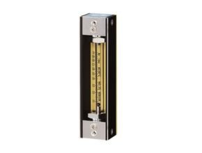
Kofloc Kofloc RK1000 Series Purge Flow Meter
Purge Flowmeter Kofloc RK1000 is a glass tube float-type flowmeter materialized through our all-out effort at streamlining the production line to offer users a low-cost model that can be shipped in a reduced period of delivery. While it is outstandingly compact(total length of the smallest type: 80 mm), it provides high performance in stability that bears comparison with any high precision models and is optimum to form a part of the customer’s scientific instrumentation system.
Features Kofloc RK1000
- Superior stability
- Economical
- Super-compact
- Wide variations
ApplicationsKofloc RK1000
- For integration into the equipment panel
- For gas purge systems
- For measurement of welding gas flows
- For various types of analyzers
- For semiconductor manufacturing equipment
Standard Specifications Kofloc RK1000
- Fluids: Air, N2, O2, H2, He, Ar, and CO2 (Calibration by actual gas)
- For other gases, consultation is necessary regarding whether conversion conditions or
calibration by actual gas is to be used.
- For other gases, consultation is necessary regarding whether conversion conditions or
- Flow range (Full scale) : 1L,2L,3L,5L,10L,15L,20L/MIN
- Accuracy: FS±5%(Measurement point)
- Proof pressure:
- 0.8MPa for 5L/MIN or less
- 0.5MPa for 10 L/MIN or more
- Available scale: 10:1
- Body block and some other components :
- S : SUS304; SUS303
- BS: Brass
- Tapered tube: S & BS: Pyrex®, glass
- Packing :
- S : FKM
- BS : NBR
- Float : * S & BS : Pyrex,SUS316, glass
- Protective cover :* S & BS: Acrylic resin
- (Temperature resistance) : * S & BS : MAX60°
- Connection : * S & BS : Rc1/8(Standard);Rc1/4(Optional)
Source : www.kofloc.co.jp
Another Article:
- Ryuki FLO-PL-4D Small Purge Flow Meter
- Gas Variable Area Flow Meter Kofloc
- Kofloc Purge Flow Meter Model RK1050 Series
- Kofloc Purge Flow Meter with Needle Valve Model RK1600R
- Kofloc Purge Flow Meter with Needle Valve Model RK1650