

Description
The tank mounted return line filter with filter element according to Bosch Rexroth standard is located in the return line for direct attachment onto the tank of a hydraulic or lubrication system. Optionally, the filter can also be installed as an inline filter in a pipeline.
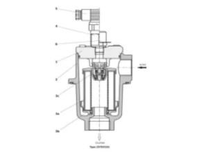
The Bosch Rexroth 25 filter basically consists of filter cover (1), filter housing (2), filter element (3), as well as a bypass valve (3c). Optionally, the filter is equipped with maintenance indicator (4). With an electrical maintenance indicator the connection can be carried out via different mating connectors (5).
Bosch Rexroth 25TE is used as an inline filter, a threaded ring (6) must be configured with the order data – additional data “M” and a maintenance indicator waivered. If necessary, the customer must provide an external differential pressure measurement.
During operation, the hydraulic fluid reaches the filter housing via the inlet; here, it flows through the filter element (3a) from the outside to the inside and is cleaned according to the filter rating. The dirt particles filtered out collect in the dirt retainer (3b) and in the filter element (3a).
Via the outlet, the filtered hydraulic fluid enters the tank. When the element becomes fully contaminated, the required element change is signaled by the maintenance indicator (4 or 5). There are several maintenance indicators to choose from :
- Mechanical visual maintenance indicator
- Electrical maintenance indicator with three possible mating connectors (mating connectors are to be ordered separately)
- Electrical maintenance indicator ATEX with pre-assembled mating connector
Refer to “Maintenance indicator” for details.
Feature
- Filters for tank mounting and inline installation
- Special highly efficient filter media
- Filtration of very fine particles and high dirt holding capacity across a broad pressure differential range
- High collapse resistance of the filter elements
- Optional equipment with different back pressureindicator
- Bypass valve in the filter element
- Filter element with integrated dirt retainer
Specification Bosch Rexroth 25TE
General
| Type / version | 25TE | |||||
| Size | 101 | 201 | 351 | 1C051 | ||
| Component series | 2X | |||||
| Ambient temperature range 1) | -10 … +65 °C | |||||
| Storage conditions | NBR seal 2) | -40 … +65 °C | ||||
| FKM seal 2) | -20 … +65 °C | |||||
| Installation position | vertical | |||||
| Filtration direction | From the outside to the inside | |||||
| Fatigue strength according to ISO 10771 | Load cycles | > 10? with max. operating pressure | ||||
| Material | Filter cover | Grey cast iron | DucCtile iron | |||
| Filter housing | Grey cast iron | Ductile iron | ||||
| Bypass valve | Plastic PA 6 | |||||
| Seals | NBR / FKM | |||||
| Weight | 3 kg | 5.8 kg | 12 kg | 21.5 kg | ||
| Volume | 0.5 l | 1 l | 2.5 l | 6.2 l | ||
| Surface requirementfor tank opening | Roughness depth | Rz max. | 25 µm | |||
| Flatness | tE max. | 200 µm | ||||
- 1)short periods down to -30 °C
- 2)max. relative air humidity 65 %
Important information on hydraulic fluids!
- For further information and data on the use of other hydraulic fluids, please refer to data sheet 90220 or contact us!
- Flame-resistant – containing water: Due to possible chemical reactions with materials or surface coatings of machine and system components, the service life with these hydraulic fluids may be less than expected. Filter materials made of filter paper P must not be used, filter elements with glass fiber filter material are to be used instead.
- Bio-degradable: If filter materials made of filter paper are used, the filter life may be shorter than expected due to material incompatibility and swelling.
Hydraulic
| Type / version | 25TE | ||||
| Size | 101 | 201 | 351 | 1051 | |
| Max. operating pressure | 25 bar | ||||
| Cracking pressure | Bypass valve | 3 ±0.3 bar | |||
| Hydraulic fluid temperature range | -10 … +100 °C | ||||
| Minimum conductivity of the medium | 300 pS/m | ||||
| Filtration direction | From the outside to the inside | ||||
Compatibility with permitted hydraulic fluids
| Hydraulic fluid | Classification | Suitable sealing materials | Suitable adhesive | Standards | |
| Mineral oil | HLP | NBR | Standard | DIN 51424 | |
| Bio-degradable | Insoluble in water | HETG | NBR | VDMA 24568 | |
| HEES | FKM | ||||
| Soluble in water | HEPG | FKM | VDMA 24568 | ||
| Flame-resistant | Water-free | HFDU, HFDR | FKM | VDMA 24317 | |
| Containing water | HFAS | NBR | DIN 24320 | ||
| HFAE | NBR | ||||
| HFC | NBR | VDMA 24317 | |||
| Skydrol | ? | EPDM | Special “H” | ? | |
Important information on hydraulic fluids!
- For further information and data on the use of other hydraulic fluids, please refer to data sheet 90220 or contact us!
- Flame-resistant – containing water: Due to possible chemical reactions with materials or surface coatings of machine and system components, the service life with these hydraulic fluids may be less than expected. Filter materials made of filter paper P must not be used, filter elements with glass fiber filter material are to be used instead.
- Bio-degradable: If filter materials made of filter paper are used, the filter life may be shorter than expected due to material incompatibility and swelling.
Tightening torques (Dimensions in mm)
Mounting filter cover
| Series 25TE | 101 | 201 | 351 | 1051 | |
| Screw cover fastening | M5 x 20 | M8 x 20 | M10 x 25 | M16 x 25 | |
| Quantity | 4 | ||||
| Recommended property class of screw | 08.08 | ||||
| Tightening torque with ?total = 0.14 | Nm | 6 ± 0,6 | 25 ± 2,5 | 50 ± 5,0 | 150 ± 15 |
Tank mounting
| Series 25TE | 101 | 201 | 351 | 1051 | |
| Tank mounting screw | M5 | M6 | M8 | M12 | |
| Quantity | 4 | ||||
| Recommended property class of screw | 08.08 | ||||
| Tightening torque with ?total = 0.14 | Nm | 7 ± 0,7 | 13 ± 1,3 | 18 ± 1,8 | 60 ± 6 |
Maintenance indicator
| Series 25TE | 101 | 201 | 351 | 1051 | |
| Mechanical/visual maintenance indicator | Nm | 30 ± 3 | |||
| Electric maintenance indicator; brass | Nm | max. 40 | |||
| Electric maintenance indicator; stainless steel ATEX | Nm | max. 70 | |||
| Cubic connector screw M3 switching element EN-175301-803 | Nm | 0,5 … 0,6 | |||
| Threaded coupling for venting | Nm | max. 40 | |||
Complete filter without maintenance indicator
| Use/assignment | II 2G | II 2D | |
| Assignment | Ex II 2G c IIC TX | Ex II 2D c IIC TX | |
| Conductivity of the medium | min. | 300pS/m | |
| Dust accumulation | max. | 0.5 mm | |
Electronic maintenance indicator in the intrinsically safe electric circuit
| Use/assignment | II 1G | II 1D | |
| Assignment | II 1GD Ex ia IIC TX°C X; II 1GD Ex ia IIIC TX°C X | ||
| Perm. intrinsically safe electric circuit | Ex ia IIC | Ex ia IIIC | |
| Switching voltage Ui | max. | 20 V AC/DC | |
| Switching current Ii | max. | 200 mA | |
| Switching power Pi | max. | 1 W | |
| Maximum surface temperature | – | 100 °C 1) | |
| Inner capacity Ci | neglectable | ||
| Inner inductivity Li | neglectable | ||
| Dust accumulation | max. | – | 0.5 mm |
1)The temperature depends on the temperature of the medium in the filter and must not exceed the value specified here.
Read more article:
- Lika Electronic – Smart Encoders & Actuators
- Disc and Weir Oil Skimmers
- Firetrol Mark IIXG Diesel Engine Fire Pump Controllers
- Lenc Energy Gas Solenoid Valve
- Helical Gear Reducer Hansen M4 ACC