
Description
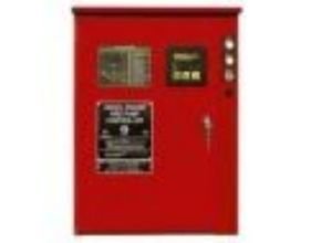
Firetrol Mark IIXG Diesel Engine Fire Pump Controllers combined with automatic and manual Mark IIXG-based diesel engine fire pump controllers are intended for starting and monitoring fire pump diesel engines. The controller monitors, displays, and records fire pump system information. Diesel engine fire pump controllers are available in 12 or 24 volts, work with lead acid or Nickel-Cadmium batteries, and are designed to operate seamlessly with either mechanical or electronic engine types.
Operator Interfaces
The fire pump controllers feature an operator interface with a user keypad. The interface monitors and displays motor operating conditions, including all alarms, events, and pressure conditions. All alarms, events, and pressure conditions are displayed with a time and date stamp. The display is a 128×64 Backlit LCD capable of customized graphics and Cyrillic type character display. The display and interface are NEMA rated for Type 2, 3R, 4, 4X, and 12 protection and is fully accessible without opening the controller door. The user interface utilizes multiple levels of password protection for system security. A minimum of 3 password levels are provided.
Main Fire Pump Controller
The Mark IIxg FTA 3100M provides a variable frequency drive (VFD) in a PID process control loop to control the speed of a centrifugal pump for the purpose of limiting the system pressure in a sprinkler system used for fire protection. The controller shall control a fire pump motor having the horsepower, voltage, phase and frequency rating shown on the plans and drawings. The controller shall be equipped with both automatic and manual bypass to start and run the motor should a problem arise with the VFD. The controller shall be provided with a full-voltage starting bypass.
Withstand Ratings (Short Circuit Current Ratings)
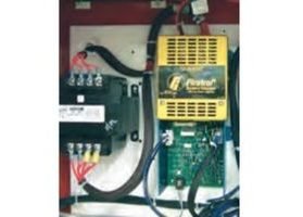
All controller components shall be front-mounted, wired, and front access for maintenance. The minimum withstands rating of the controllers shall not be less than 100,000 Amps RMS Symmetrical at 200-600 Volts*. If the available system fault current exceeds these ratings, the controllers shall be supplied with a withstand rating of 150,000 or 200,000 Amps RMS Symmetrical, as required. *Note: 100,000 Amp withstand rating not available in some larger horsepowers. Consult the factory for details.
Isolation Switch and Circuit Breaker
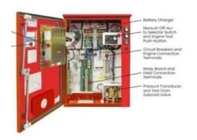
The controller shall include a motor-rated combination isolating disconnect switch/circuit breaker, mechanically interlocked and operated with a single, externally mounted handle. When moving the handle from OFF to ON, the interlocking mechanism shall sequence the isolating disconnect switch ON first, and then the circuit breaker. When the handle is moved from ON to OFF, the interlocking mechanism shall sequence the circuit breaker OFF first, and then the isolating disconnect switch.
The isolating disconnect switch/circuit breaker shall be mechanically interlocked so that the enclosure door cannot be opened with the handle in the ON position except by a hidden tool-operated bypass mechanism. The isolating disconnect switch/circuit breaker shall be capable of being padlocked in the OFF position for installation and maintenance safety, and shall also be capable of being locked in the ON position without affecting the tripping characteristics of the circuit breaker.
The controller doors all have a locking-type handle and three-point cam and roller vault-type hardware. The circuit breaker trip curve adjustment shall be factory set, tested, and sealed for the full load amps of the connected motor. The circuit breaker shall be capable of being field tested to verify actual pick up, locked rotor, and instantaneous trip points after field installation without disturbing incoming line and load conductors.
Battery Chargers
The controllers are supplied with two fully automatic, 200 amp hour, 4-step battery chargers. The chargers feature Switching Technology and 10Adc Pulse-Width Modulated Output Current. The 4-step charging cycle is as follows:
- Step 1 – Qualification Stage During this stage, the battery charger checks the batteries to insure they can accept a fast charge. It also scans for missing or defective batteries. A fault will be given if a missing or faulty battery is detected.
- Step 2 – Fast Charge Stage Charges the batteries until they reach peak voltage.
- Step 3 – Bulk Charge Stage Charges the batteries at a constant potential of peak voltage until the current reaches 500mA.
- Step 4 – Float Charge Stage Trickle charges the batteries to maintain peak potential.
Approvals
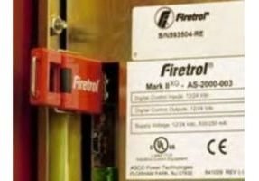
Firetrol fire pump controllers are listed by Underwriters’ Laboratories, Inc., in accordance with UL218, Standard for Fire Pump Controllers, CSA, Standard for Industrial Control Equipment, and approved by Factory Mutual. They are built to meet or exceed the requirements of the approving authorities as well as NEMA and the latest editions of NFPA 20, Installation of Centrifugal Fire Pumps, and NFPA 70, National Electrical Code.
Digital Status/Alarm Messages
The digital display indicates text messages for the status and alarm conditions of:
- Engine Run
- Remote Start
- Minimum Run Time
- System Battery Low-Off Delay Time
- Manual Engine Crank
- The engine Fails to Start
- Electronic Control
- Low Suction Pressure Module (ECM) Warning
- Drive Not Installed
- ECM Failure
- Disk Error
- Low Suction Pressure
- Disk Near Full PLD (pressure limiting
- Pressure Error driver)
- Sequential Start Time
- High Raw Water Temp.
- Crank/Rest Time Cycle
- Clogged Raw Water
- Low Engine Temp. Stainer
Interstitial/Fuel Spill The Sequential Start Timer and Minimum Run Timer/Off Delay Times are displayed as numeric values reflecting the value of the remaining time.
LED Visual Indicators
LED Visual Indicators LED indicators, visible with the door closed, indicate:
- AC Power Available
- Alarm
- Main Sw. in Auto
- Main Sw. in Manual
- System Pressure Low
- Engine Running
- The engine Fail to Start
- Engine Temperature High
- Engine Oil Pressure Low
- Engine Overspeed
- Engine Alternate ECM
- Engine Fuel Injector Malfunction
- Fuel Level Low
- Automatic Shutdown Disabled
- Charger Malfunction
- Battery #1Trouble
- Battery #2 Trouble
Data Logging
The user interface monitors the system and logs the following data:
- Number of Calls/Starts
- Engine Total Run Time
- Last Run Time
- Controller Power On Time
- Last Start
- Minimum System Pressure
- Maximum System Pressure
- Last High Temperature
- Last Low Oil Pressure
- Last Engine Overspeed
- Last Low Fuel Level
- Last Charger Fail
- Last Battery Trouble
- Battery #1 Volts
- Battery #2 Volts
- Battery #1 Amps
- Battery #2 Amps
Event Recording
Memory – The controller records all operational and alarm events to system memory. All events are time and date stamped and include an index number. The system memory has the capability of storing 3000 events and allows the user access to the event log via the user interface. The user can scroll through the stored messages in groups of 1 or 10.
USB Host Controller
The controller is equipped with a built-in USB Host Controller. A USB port capable of accepting a USB Flash Memory Disk is provided. The controller saves all operational and alarm events to the flash memory on a daily basis. Each saved event is time and date stamped. The total amount of historical data saved depends on the size of the flash disk utilized. The operator can save settings and values to the flash disk on demand via the user interface.
Standard Features
Firetrol® Variable Speed Electric Fire Pump Controllers provide a variable frequency drive (VFD) in a PID process control loop to control the speed of a centrifugal pump for the purpose of limiting system pressure in a fire sprinkler system.
Controller Features:
- Disconnect the Switch / Circuit Breaker
- Manual Start & Stop Push-Buttons
- Door Mounted Interface
- Weekly Test Timer
- Data Logging
- True RMS Metering
The following are included as standard with each controller:
- Voltage surge protector
- Main Disconnect Switch sized for connected motor horsepower and voltage
- Fire pump Circuit Breaker
- Single handle Isolating Disconnect Switch/Circuit Breaker mechanism
- Motor contactor
- Emergency Manual Run Mechanism to mechanically close motor contactor contacts in an emergency condition
- Built-in Start and Stop push-buttons to bypass automatic start circuits
- Minimum Run Timer / Off Delay Timer
- Daylight Savings Time Option
- Weekly Test Timer
- Elapsed Time Meter
- Door-mounted display/interface panel featuring a 128 x 64 pixel backlit LCD Graphical Display, Membrane Type User Control Push-buttons and easy to read LED Indicators
- Enclosures: The controller components shall be housed in a NEMA Type 12 (IEC IP54) drip-proof, floor-mounted enclosure.
Reference: firetrol.com
Read More Articles :
- Power-Genex Valve Position Monitor
- Dayton Motors – Grainger Industrial Supply
- Wichita Clutch Air Brake
- Lenc Energy Gas Solenoid Valve
- Chester Machine Tools
- Helical Gear Reducer Hansen M4 ACC
- Cyclo Gearmotor with Torque Limiter Sumitomo Drive Technologies
- Drizit Oil and Chemical Pollution Control
- SEISA GC Coupling Sumitomo Drive Technologies
- Hansen P4 Multistage – Horizontal