
The Measurement Principle
Each mass flow meter has two measuring tubes. The oscillating system is driven by two controlled electromagnetic excitation coils. As liquids or gases flow through the oscillating omega tubes, the Coriolis force is created and causes a slight deflection of the two measuring tubes from their original shape.
The opposing tubes are referenced to each other and the changes in deflection are proportional to the mass flow rate. In practice, the referencing is done by attaching small pickup coils that generate sinusoidal voltages. The degree of deviation of the phase shift is directly proportional to the mass flow.
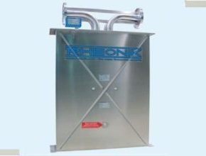
The RHM 60 is a robust sensor designed for 4? line sizes. Its availability in a variety of wetted materials and wide pressure/temperature ratings allow it to be used in applications throughout all industries.
- Range: 30 kg/min up to 3000 kg/min
- Pressure: up to 430 bar (6236 psi)
- Temperature: -196°C (-321°F) up to +350°C (662°F)
- Accuracy: 0.1 % of rate
- Materials: SS 316L / SS 316Ti, Super Duplex – 1.4410, Alloy C22 – 2.4602
- Process Connection: 4″ up to 4″

Features
- Standard pressure ratings up to 490 bar (7107 psi)
- Temperature ratings from -196 to 350°C (-320 to 662°F)
- Mass flow uncertainty down to 0.15%
- Density uncertainty down to 0.5%
- Repeatability better than 0.05%
- Typical measuring ranges between 60 and 3000 kg/min
- Accurately measure low flow rates down to 45 kg/min
- Unique robust torsion has driven the oscillation system
- Process connection customization available
- Approved for use in hazardous areas
- Stainless steel case
- Remote and compact transmitter versions are available
Applications
- Plant Balance
- Terminal Transfer
- Asphalt/Bitumen and Other High-Temperature Fluids
- Viscous Fluids
- Reactor Charging
- Batching
- Barge, Ship, Rail Car, and Truck Filling
Benefits
- The torsion oscillator design assures a stable and drift-free measurement with excellent signal-to-noise ratios
- Resilient to external noise and vibration
- Insensitive to pipe pressure changes
- Robust tube wall thickness provides increased operational safety in abrasive Applications
- Corrosion-resistant
- Long sensor life is guaranteed due to low mechanical stresses in the meter mechanism
- No moving parts to wear or fail
RHM60 General Specifications
| Nominal Flow (Q???)* | 2500 kg/min (5512 lb/min) |
| Maximum Flow (Q???)* | 3000 kg/min (6614 lb/min) |
| Typical Minimum Flow (Q???)* | 30 kg/min (66 lb/min) |
| Operating Temperature | Fluid temperature range options cover applications from -196°C to +350°C (-320°F to +662°F). For integral transmitter versions please refer to the transmitter datasheet |
| Ambient Temperature | -50 °C to +80 °C (-60 °F to +180 °F) (standard) |
| Pressure Ratings | Up to 490 bar / 7107 psi – dependent upon material |
| Electrical Connection Sensor | M20 x 1.5 standard cable entry for JM, SM terminal box versions |
| w/o Integral Transmitter | Optional entries available : ½” NPT or M25 x 1.5 (only for SM) or ¾” NPT (only for SM) |
| Max. cable length to remote RHE transmitter 100 m / 328 ft | |
| Sensor Enclosure Materials | Stainless steel 304 (standard), SS 316 (optional) |
| Coated aluminum terminal box, SS 316 terminal box (optional) | |
| Enclosure Type | Protection class IP66 / NEMA 4X with Standard Temperature Range (Option N1/NA); IP65 / NEMA 4 for Extended Temperature Ranges (Option E2 / E3 / H4) |
| Wetted Materials | 1.4571 (SS 316Ti), 1.4410 (SuperDuplex) – standard |
| 2.4602 (Alloy C22) – consult Factory | |
| Additional/customer-specific materials available upon request | |
| Process Connections | Nearly any – the Rheonik AnyPipeFit Commitment. Consult the factory for types/sizes not listed |
| Pressure Rating Compliance | Europe – PED: Module A2, Module B3.1+C2 |
| Canada – CRN: Canadian Registration Number | |
| Certifications and Approvals | ATEX / IECEx Approvals for Zone 0, 1 (details see page 10) |
| North American Approvals Class I, Div. 1, 2, Gr. A, B,C, D, Zone 0, 1, 2 | |
| MID custody transfer approval (OIML R117) | |
| American Bureau of Shipping (ABS) Product Type Approval for use on marine vessels | |
| Testing and Inspection | All sensors are hydro-tested, calibrated, and supplied with a traceable calibration certificate. Customized calibration and testing services are available |
| Project Documentation and QA, Services | Rheonik offers a full set of services for large and complex engineering projects. |
| Typical services offered are, but not limited to: | |
| •Certificates of origin and conformity, mill certificates | |
| •Data books including WPAR, WQS, NDT, test & quality plans, functional testing, calibration procedures, customized packing, factory acceptance etc. | |
| •Painting to project specification | |
| •Start up and commissioning services on/offshore | |
| Options | Enclosure heating for high-temperature applications |
| Cleaning for oxygen service, … | |
| For more consult the factory |
* At Q pressure drop across a parallel tube sensor will be approximately 0.5 bar (7 psi) for H 0. Sensors can be operated at higher flow rates up to Q but the pressure drop will be higher. Typical Minimum Flow Q is the recommended lowest flow rate for an accurate measurement. Sensors will measure flow rates lower than Q but uncertainty will increase beyond 1 % of rate.
The flow rate specifications above relate to standard pressure, parallel tube, and manifold sensor versions. Models with higher pressure ratings have increased wall thickness and will have higher pressure drops.
Uncertainties and flow Measurements Turn Down
All uncertainty statements refer to reference conditions – the mass flow of water, 18 – 24 °C, 1 – 3 bar in a standard temperature, pressure, and material configuration sensor. The sensor can be used to measure gas – uncertainty values for gas equal to the liquid value plus 0.3 %. Reference conditions for gas are mass flow of natural gas, 18 – 24 °C, 35 to 100 bar in a standard temperature, pressure, and material configuration sensor.
The turn-down capability from the Qnom of the flow sensor is mainly driven by its zero-point stability. At the very low end of the measuring range, the uncertainty (u) is dominated by the zero point stability. The zero point stability of a standard sensor is: 0.000036 kg/min (0.000079 lbs/min). The zero stability of a Gold Line sensor is 0.000019 kg/min (0.000042 lbs/min).
Uncertainties from Environmental and Process Conditions
- If sensors are not zeroed at operating conditions, minor additional uncertainties can arise from elevated temperatures and pressures: ±0.00308 % of maximum flow per °C and ±0.0208 % of maximum flow per bar.
- Process temperature effect on density: additional uncertainty of ±0.000641 g/cm³ per °C difference from calibration temperature with standard density calibration and of ±0.000073 g/cm³ per °C difference from calibration temperature with enhanced density calibration. This effect can be mitigated by a simple field density adjustment at operating conditions.
- Process pressure effect on mass flow: The effect of pressure on flow measurement is 0.001 % of rate per bar. Compensation is possible by pressure sensor input (analog input or digital write) or manual value entry into the transmitter.
- Process pressure effect on density: The effect of pressure on density measurement is 0.00012 g/cc per bar. Compensation is possible by pressure sensor input (analog input or digital write) or manual value entry into the transmitter.
The types and capacities of the Coriolis Mass flow meters
Small Size Coriolis Mass Flow Sensor
Ideal for embedded systems and precise small flow applications
- RHM 015 Low Flow Mass Flow Meter flow rate
- RHM 02 Low Flow Mass Flow Meter flow rate
- RHM 03 Low Flow Mass Flow Meter flowrate
- RHM 04 Low Flow Mass Flow Meter flow rate
- RHM 06 Low Flow Mass Flow Meter flowrate
- RHM 08 Low Flow Mass Flow Meter flow rate
Medium Size Coriolis Mass Flow Sensor
Suited to industrial and process flow control and monitoring
Large Size Coriolis Mass Flow Sensor
Perfect for material movements in small and wide-scale operations
- RHM 60 Coriolis Flow Meter flow rate
- RHM 80 Coriolis Flow Mass Meter flow rate
- RHM 100 Coriolis Flow Mass Meter flow rate
- RHM 160 Coriolis Flow Mass Meter flow rate
The types of Coriolis Mass Flow Transmitter
- Rheonik RHE16 Coriolis mass flow transmitter Compact Multifunction
- Rheonik RHE15 Profibus DP Module
- Rheonik RHE21 explosion proof field mount Mass Flow Transmitter
- Rheonik RHE 26 Coriolis Mass Flow Transmitter
- Rheonik RHE 27 Coriolis mass flow transmitter
- Rheonik RHE28 Field / Wall Mount Coriolis mass flow transmitter
- Rheonik RHE45 Compact Mount Coriolis Mass Flow Transmitter
- Rheonik RHE42 Coriolis Mass Flow Transmitter
- Flow Meter Open Channel Untuk PLTU
- Instalasi Flow meter ultrasonic clamp on untuk air dingin mesin chiller
- Prosedur Instalasi Flow Meter Electromagnetic
- Meteran air Jenis flow meter Ultrasonic
- Flow meter ultrasonic clamp on untuk pipa HDPE
- Flow Meter Ultrasonic Jenis Clamp On Untuk Pipa PVC
- Harga Coriolis Mass Flow Meter
- Perlunya Resetting dan Kalibrasi Flow meter secara berkala
- Jenis Flow Meter Berdasarkan Prinsip Kerja dan Aplikasinya
- Penentuan Kapasitas Flow Meter Pada Aliran Air
- Flow Meter Ultrasonic Clamp on untuk Proses Destilasi Air Laut
- Flow Meter Ultrasonic Portable untuk Mengecek Sistem Pendingin Mesin
- Penggunaan Flowmeter Ultrasonic Pada Pengolahan air limbah