

EGE Elektronik Level Controller Descriptions
EGE Elektronik Level Controller without moveable parts are available in various versions and are extremely resistant to soiling. Capacitive level controllers are available for gases to -200 °C as well as hot glue up to +230 °C.
EGE Elektronik Level Controller PTFE and PEEK are here the preferred materials because they prevent adhesions. Opto fill sensors with glass or PSU tip do not require a medium adjustment and are simply added top the tank. These sensors are also available as explosion-proof units in accordance with ATEX. Ultrassonic sensors, pressure controllers or the capacitive high-temperature measuring probe KFA continuously monitor and log fill levels.
EGE Elektronik Level Controller Sensors – Application notes
Microwave meter
The MFP and MFM level meters for continuous monitoring of various liquids allow for an exact determination of the fill level in plastic or metal tanks of any size. The devices offer a high measurement precision. The level sensors work with numerous liquids such as water, oil or emulsions. To this end microwaves are “guided” in the measuring rod – and are reflected at the surface of the medium, and the sensor determines the fill level.
No adjustment for various media is necessary. The aluminium and AISI 316 Ti stainless steel probes are suitable for ambient temperatures between –20 and +70 °C. They are available in optional sizes between 500 and 1100 mm in length. The sensors are equipped with a G3/4 thread and are connected via an M12 plug. The fill level is transmitted to the analysis unit or SPS by means of a 4…20 mA signal.
Microwave Level Controllers
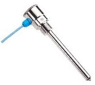
The microwave level controllers of the MFC and MFK series respond to media contact at the tip of the sensor. They are especially insensitive to soiling and build-up.The devices of the MFK series are made of stainless steel and PTFE and are equipped with a G1/2 process connection. The sensors have a length of 40 mm. Thanks to their integrated electronics, no downstream amplifier is required. The sensors do not have to be adjusted to different media, and for containers made of plastic material, no earth connection is required.
Users can adjust the sensitivity of the devices of the MFC series using a pushbutton. Thus, the sensors can distinguish between different layers of liquids (e.g. water and oil) in the containers allowing for an easy separation of liquids. The stainless steel and PTFE microwave sensors can be used for virtually all container types and sensor environments. They are also suited for use with powder or granules. The sensors are available with a length of between 120 mm and 1000 mm thus offering various different installation options.
Capacitive Sensors
EGE Elektronik Level Controller The operation of these level sensors is based on a dielectric measuring method. All media which are surround the sensors measuring electrode, built into the tip of the probe, change the state of dielectric balance between the measuring electrode and the surrounding space. This disturbance in the balance triggers a switching command inside the device. The balance can be adjusted with a built-in potentiometer so that materials with different bulk densities and correspondingly different dielectric constants can be measured optimally.
Metallic or metal clad vessels should be earthed. In the case of plastic vessels filled with electrically conductive materials, the latter should be earthed. In the case of plastic vessels filled with non-conducting materials, an earthed metal band applied on the outside of the vessel may be used as a counter-electrode.
Medium Adjustment for Capacitive Sensors
Level sensors are set in such a way that they switch upon contact with a medium. The medium adjustment should, if possible, take place without removal under operating conditions. If the built-in part of the sensor can be completely submerged or covered during operation, the adjustment must also take place in this state. If only medium contact is possible, the adjustment takes place upon contact.
The trimmer potentiometer is protected by a plastic bolt. This bolt must be removed before the desired sensitivity is set. Turning it clockwise increases the response sensitivity. The adjustment potentiometer is turned until the switch output switches through (normally-open contact). You achieve switching point safety by continuing to turn the potentiometer half a turn to one turn. Devices with a LED line are adjusted to two green LEDs. If the medium adjustment has taken place, the plastic bolt must be fixed again.
Laboratory Adjustment
lf adjustment cannot be carried out with the sensor mounted in operating position, it can be performed upon a similar vessel. It must, however, be made sure that this vessel is set upon an earthed metal plate, or that the liquid within the vessel is earthed by means of an introduced wire.
The minimum height and minimum diameter of the experimental vessel should be about 10 cm. lf setting is correct, the filling level monitor reacts correctly if 50% of the electrode diameter is covered. When mounted vertically, sensors reacts upon contact with the medium. Reaction time lag is less than 0.25 sec.
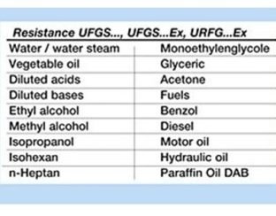
Opto-sensors UF../UR..
Optical sensors react to a change of the refraction index within the proximity of the sensor tip when being immersed into fluid. The sensor does not have to be adjusted. In rare cases, the container wall or particles within the fluid may reflect the light emitted by the sensor and thus interfere with the fluid detection. A trial run is recommended in such instances. The sensors are designed to be used with the respectively listed fluids under normal conditions. The chemical compatibility and technical suitability of the sensor should be tested when used with unlisted fluids.
Conductive Level Controller
The conductive level sensor CFC… is used for precise level-detection of conductive media. Adhesion even of highly conductive media are no problem. The electrode can be shortened by the customer. With the additional screw-on-electrode it can even be used in plastic containers. Media with a conductivity greater than 10 µS/cm will be detected.
Sensors for Explosion Hazardous Areas
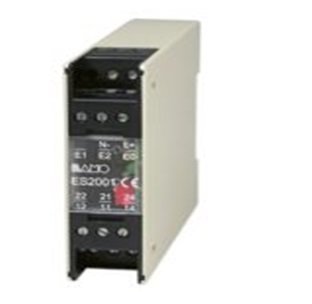
Fill level monitors for use in zone 0 or zone 20 are operated with the associated amplifiers listed in the respective connection chart. The analysis devices are always operated outside of the Ex area. Sensors of the series KGFT…Ex are used in conjunction with an intermediate amplifier, which is approved for installation in zone 1. Optical Ex sensors UFGSa…Ex can also be driven with the amplifier IKMb 123 Ex.
Level Sensors – Instructions for mounting
At the side installation of capacitive sensors we prefer to put the sensor tip on an angle of 20 degree to protect sedimation. The sensors should be protected against damages by side power effects for example by blungers.
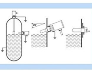
For flush mounting, the sensor can be built into influencing material up to its active surface without changing its characteristics. For non-flush mounting, a metal-free zone around the sensor must be allowed for. A free zone to the material opposite the sensor must be maintained for all sensors.
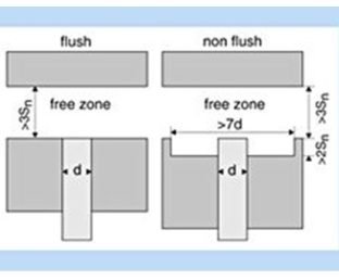
Collocation
When collocating the sensors, a minimum separation must be kept between the devices in order to avoid mutual influence. When in doubt, a test should be conducted under application conditions. For capacitive sensors, the lateral separation from one another must correspond to at least twice the diameter of the sensor. For separations greater than eight times the diameter no mutual influence is to be expected. For oppositely mounted sensors, a minimal separation of eight times the nominal switching separation should be allowed for.
Threads
The threads of the sensors in this prospectus are manufactured to DIN ISO 228-1, tolerance class B. They are designated with (“) or (G). If it is necessary to combine different threads, e.g. the sensor-thread made to DIN ISO 228-1 and an inner thread made to DIN ISO 229, such inner thread must be widened by a thread drill.
Read More Articles : EGE Elektronik Ultrasonic Sensor
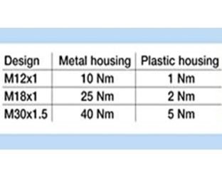
Torques
In order to prevent destruction of the threaded bushing during fitting, the following maximum torques must not be exceeded:
Sealings
The sealings used for our sensors are made of PTFE, NBR, FPM or AFM. For water applications with water temperatures up to 150 °C and with pressures less than 5 bar, EDPM O-rings must be used. If the temperatures exeed 100 °C or the pressures are higher special sealings are necessary (2). When ordering sensors for such applications, such special sealings must be ordered too.
Instructions for operation
Serial connection
For the serial connection of two wire or three wire sensors the individual voltage drops are added together. Therefore there is a lesser operational voltage at the disposal of the load. The addition of the switch-on delay times should be noted.
Parallel connection
The parallel connection of two wire sensors can only be conditionally recommended since the residual currents are added together and flow through the load. For the parallel connection of three wire sensors, the current consumption of the individual devices is added together. Since this current does not flow through the load, the maximum number of parallel connectable three wire sensors depends only on the power supply.
Approval for safety applications
Sensors for personal security must have a qualification approval according to EN 61508 and must be labeled accordingly. Sensors that are not labeled must not to be used for applications of this kind.
Read More Articles :
- EGE Elektronik Inductive Proximity Switches
- EGE Elektronik Ultrasonic Sensor
- Crouzet Mechatronic Component
- Lefoo Industrial Components
- Kyoritsu Electrical Instrument