
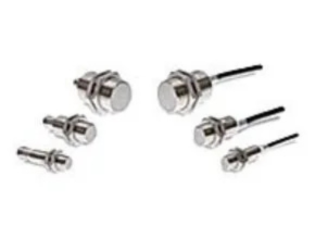
Omron 2 Wire Proximity Sensor use high-frequency oscillation. They resist heat, chemicals, and water better than Rectangular Sensors. They are available in both shielded and unshielded models.
Proximity Sensors are available in models using high-frequency oscillation to detect ferrous and non-ferrous metal objects and in capacitive models to detect non-metal objects. Models are available with environment resistance, heat resistance, resistance to chemicals, and resistance to water.
Omron E2EH-X D DC 2 Wire Features
- Improved resistance to detergents and rusting
- Applicable to 120?C (with DC 3-wire connection) (Heat resistance verified to 1,000 hours.)
- Resists typical detergents and disinfectants used in the food industry
- Water-resistant under high-temperature, high-pressure cleaning based on DIN 40050-9. (Pressure: 8,000 to 10,000 kPa, Water temperature: 80?C, For 30 s at all angles
Specifications
| Size Shielded | M12 | M18 | M30 | |
| Shielded | ||||
| Item Model | E2EH-X3D@ | E2EH-X7D@ | E2EH-X12D@ | |
| Sensing distance | 3 mm | 7 mm | 12 mm | |
| Set distance *1 | 0 to 2.4 mm | 0 to 5.6 mm | 0 to 9.6 mm | |
| Differential travel | 15% max. of sensing distance | |||
| Detectable object | Ferrous metal (The sensing distance decreases with non-ferrous metal. Refer to Engineering Data (Reference Value) on page 6.) | |||
| Standard sensing object | Iron, 12 ´ 12 ´ 1 mm | Iron 21 ´ 21 ´ 1 mm | Iron 36 ´ 36 ´ 1 mm | |
| Response frequency *2 | 500 Hz | 300 Hz | 100 Hz | |
| Power supply voltage (operating voltage range) | 12 to 24 VDC, ripple (p-p): 10% max. | |||
| (10 to 32 VDC, however, 24 VDC max. at temperatures over 100°C) | ||||
| Leakage current | 0.8 mA max. | |||
| Control out- put | Load current | 3 to 100 mA (however, 3 to 50 mA at 100 to 110°C) | ||
| Residual voltage *3 | Polarity Models: 3 V max. | |||
| No polarity Models: E2EH-X@D@-T: (5 V max. *3 (Load current: 100 mA, Cable length 2 m) | ||||
| Indicators | D1 Models: Operation indicator (red), Setting indicator (yellow) D2 Models: Operation indicator (yellow) | |||
| Operation mode (with sensing ob- ject approaching) | D1 Models: NO Refer to the timing charts under I/O Circuit Diagrams on page 7 for details. D2 Models: NC | |||
| Protection circuits | Surge suppressor, Load short-circuit protection | |||
| Ambient temperature range | Operating: 0 to 100°C (0 to 110°C 1,000 h) *4 Storage: -25 to 70° (with no icing or condensation) | |||
| Ambient humidity range | 35% to 95% | |||
| Temperature influence | ±10% max. of sensing distance at 23°C in the temperature range of 0 to 70°C. | |||
| ±15% max. of sensing distance at 23°C in the temperature range of 70 to 100°C. | ||||
| -15% to +20% of sensing distance at 23°C in the temperature range of 100 to 110°C. | ||||
| Voltage influence | ±10% max. of sensing distance at rated voltage in the 15% rated voltage range. | |||
| Insulation resistance | 50 MÙ min. (at 500 VDC) between current-carrying parts and case | |||
| Dielectric strength | 1,000 VAC, 50/60 Hz for 1 min between current-carrying parts and case | |||
| Vibration resistance | Destruction: 10 to 55 Hz 1.5-mm double amplitude for 2 hours each in X, Y and Z directions | |||
| Shock resistance | Destruction: 1,000 m/s2, 10 times each in X, Y and Z directions | |||
| Degree of protection | IEC IP67, DIN 40050-9 IP69K *5 | |||
| Connection method | Pre-wired Models (Standard cable length 2 m), Connector Models | |||
| Weight (packed state) | Pre-wired Models | Approx. 80 g | Approx. 145 g | Approx. 220 g |
| Connector Models | Approx. 30 g | Approx. 55 g | Approx. 125 g | |
| Materials | Case, clamping nut | Stainless steel (SUS316L) | ||
| Sensing surface | PBT | |||
| Cable | Heat-resistant PVC cable (Pre-wired model) | |||
| Accessories | Instruction manual | |||
*1. Use the yellow indicator on D1 Models as a guide.
*2. The response frequency is an average value.
Measurement conditions are as follows: standard sensing object, a distance of twice the standard sensing object, and a set distance of half the sensing distance.
*3. The residual voltage of each E2EH-X@D@ DC 2-Wire Model is 5 V. When connecting to a device, make sure that the device can withstand the residual voltage. (Refer to page 9.)
*4. Operation with power supplied for 1,000 h has been verified at 110°C. Do not bend the cable repeatedly at 100°C or higher.
*5. IP69K Degree of Protection Specification
IP69K is a protection standard against high temperature and high-pressure water defined in the German standard DIN 40050, Part 9. The test piece is sprayed with water at 80°C at a water pressure of 80 to 100 BAR using a specified nozzle shape at a rate of 14 to 16 liters/min.
The distance between the test piece and nozzle is 10 to 15 cm, and water is sprayed horizontally for 30 seconds each at 0°, 30°, 60°, and 90° while rotating the test piece on a horizontal plane.
Download Catalog: E2EH-X D DC 2-Wire Models, Omron-Proximity Sensor
Omron Long Distance E2EM-X@X@ DC 2-Wire Models
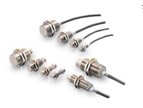
Features
- Long-distance detection at up to 30 mm enables secure mounting with reduced problems due to the workpiece
- No polarity for easy wiring with DC 2-wire
- Cable protector provided as a standard
Specifications
| Size Shielded | M12 | M18 | M30 | |||
| Shielded | Shielded | Unshielded | Shielded | Unshielded | ||
| Item Model | E2EM-X4X@ | E2EM-X8X@ | E2EM-X16MX@ | E2EM-X15X@ | E2EM-X30MX@ | |
| Sensing distance | 4 mm ±10% | 8 mm ±10% | 16 mm ±10% | 15 mm ±10% | 30 mm ±10% | |
| Set distance *1 | 0 to 3.2 mm | 0 to 6.4 mm | 0 to 12.8 mm | 0 to 12 mm | 0 to 24 mm | |
| Differential travel | 15% max. of sensing distance | |||||
| Detectable object | Ferrous metal (The sensing distance decreases with non-ferrous metal. Refer to Engineering Data on page 4.) | |||||
| Standard sensing object | Iron, 12 ´ 12 ´ 1 mm | Iron, 18 ´ 18 ´ 1 mm | Iron, 45 ´ 45 ´ 1 mm | Iron, 30 ´ 30 ´ 1 mm | Iron, 70 ´ 70 ´ 1 mm | |
| Response frequency *2 | 1 kHz | 0.5 kHz | 0.4 kHz | 0.25 kHz | 0.1 kHz | |
| Power supply voltage (operating voltage range) | 12 to 24 VDC (10 to 30 VDC), ripple (p-p): 10% max. | |||||
| Leakage current | 0.8 mA max. | |||||
| Con- trol out- put | Load current | 3 to 100 mA | ||||
| Residual volt- age *3 | 5 V max. (Load current: 100 mA, Cable length: 2 m) | |||||
| Indicators | X1 Models: Operation indicator (red), Setting indicator (green) X2 Models: Operation indicator (red) | |||||
| Operation mode (with sensing object approaching) | X1 Models: NO Refer to the timing charts under I/O Circuit Diagrams on page 5 for details. X2 Models: NC | |||||
| Protection circuits | Surge suppressor, Load short-circuit protection | |||||
| Ambient temperature range | Operating: -25 to 70°C, Storage: -40 to 85°C (with no icing or condensation) | |||||
| Ambient humidity range | Operating/Storage: 35% to 95% (with no condensation) | |||||
| Temperature influence | ±15% max. of sensing distance at 23°C in the temperature range of -25 to 70°C | |||||
| Voltage influence | ±1% max. of sensing distance at rated voltage in the rated voltage ±15% range | |||||
| Insulation resistance | 50 MÙ min. (at 500 VDC) between current-carrying parts and case | |||||
| Dielectric strength | 1,000 VAC, 50/60 Hz for 1 minute between current-carrying parts and case | |||||
| Vibration resistance | Destruction: 10 to 55 Hz, 1.5-mm double amplitude for 2 hours each in X, Y, and Z directions | |||||
| Shock resistance | Destruction: 1,000 m/s2 10 times each in X, Y, and Z directions | |||||
| Degree of protection | IEC 60529 IP67, in-house standards: oil-resistant | |||||
| Connection method | Pre-wired Models (Standard cable length: 2 m) | |||||
| Weight (packed state) | Approx. 60 g | Approx. 130 g | Approx. 150 g | Approx. 180 g | Approx. 210 g | |
| Case | Nickel-plated brass | |||||
| Sensing sur- face | PBT | |||||
| Clamping nuts | Nickel-plated brass | |||||
| Materi- als | Toothed washer | Zinc-plated iron | ||||
| Accessories | Instruction manual | |||||
Download Catalog: E2EM, Omron-Long-distance Proximity Sensor
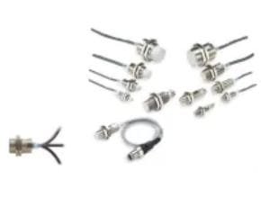
Omron Standard Proximity Sensor E2E-X T1 AC/DC 2-Wire Model

Features and Benefits
- Standard Sensors for detecting ferrous
- A wide array of variations. Ideal for a variety of
- Models with different frequencies are also available to prevent mutual
- Superior environment resistance with standard cable made of oil-resistant PVC and sensing surface made of a material that resists cutting
- Useful to help prevent
- Cable protector provided as a standard feature
Ratings and Specifications
| Size Shielded | M12 | M18 | M30 | |
| Shielded | ||||
| Item Model | E2E-X3T1 | E2E-X7T1 | E2E-X10T1 | |
| Sensing distance | 3 mm ±10% | 7 mm ±10% | 10 mm ±10% | |
| Set distance | 0 to 2.4 mm | 0 to 5.6 mm | 0 to 8 mm | |
| Differential travel | 10% max. of sensing distance | |||
| Detectable object | Ferrous metal (The sensing distance decreases with non-ferrous metal. Refer to Engineering Data on page 17.) | |||
| Standard sensing object | Iron, 12 ´ 12 ´ 1 mm | Iron, 18 ´ 18 ´ 1 mm | Iron, 30 ´ 30 ´ 1 mm | |
| Response frequency *1 | DC | 1 kHz | 0.5 kHz | 0.4 kHz |
| AC | 25 Hz | |||
| Power supply voltage (operating voltage range) *2 | 24 to 240 VDC (20 to 264 VDC) | |||
| 48 to 240 VAC (40 to 264 VAC) | ||||
| Leakage current | DC: 1 mA max. | |||
| AC: 2 mA max. | ||||
| Load current | 5 to 100 mA | |||
| Control output | Residual voltage | DC: 6 V max. (Load current: 100 mA, Cable length: 2 m) AC: 10 V max. (Load current: 5 mA, Cable length: 2 m) | ||
| Indicators | Operation indicator (red), Setting indicator (green) | |||
| Operation mode (with sensing object approaching) | NO (Refer to the timing charts under I/O Circuit Diagrams on page 21 for details.) | |||
| Protection circuits | Load short-circuit protection (20 to 40 VDC only), Surge suppressor | |||
| Ambient temperature range | Operating: -25 to 70°C, Storage: -40 to 85°C (with no icing or condensation) | |||
| Ambient humidity range | Operating/Storage: 35% to 95% (with no condensation) | |||
| Temperature influence | ±10% max. of sensing distance at 23°C in the temperature range of -25 to 70°C | |||
| Voltage influence | ±1% max. of sensing distance at rated voltage in the rated voltage ±15% range | |||
| Insulation resistance | 50 MÙ min. (at 500 VDC) between current-carrying parts and case | |||
| Dielectric strength | 4,000 VAC, 50/60 Hz for 1 minute between current-carrying parts and case | |||
| Vibration resistance | Destruction: 10 to 55 Hz, 1.5-mm double amplitude for 2 hours each in X, Y, and Z directions | |||
| Shock resistance | Destruction: 1,000 m/s2 10 times each in X, Y, and Z directions | |||
| Degree of protection | IEC 60529 IP67, in-house standards: oil-resistant | |||
| Connection method | Pre-wired Models (Standard cable length: 2 m) | |||
| Weight (packed state) | Approx. 80 g | Approx. 140 g | Approx. 190 g | |
| Case | Nickel-plated brass | |||
| Sensing surface | PBT | |||
| Clamping nuts | Nickel-plated brass | |||
| Materials | Toothed washer | Zinc-plated iron | ||
| Accessories | Instruction manual | |||
Download Catalog: Standard Proximity Sensor E2E
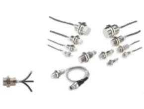
Omron Standard Proximity Sensor E2E-X AC 2-Wire Model
Features and Benefits
- Standard Sensors for detecting ferrous
- A wide array of variations. Ideal for a variety of
- Models with different frequencies are also available to prevent mutual
- Superior environment resistance with standard cable made of oil-resistant PVC and sensing surface made of a material that resists cutting
- Useful to help prevent
- Cable protector provided as a standard feature
Ratings and Specifications
| Size Shielded | M8 | M12 | M18 | M30 | |||||
| Shielded | Unshielded | Shielded | Unshielded | Shielded | Unshielded | Shielded | Unshielded | ||
| Item Model | E2E-X1R5Y@ | E2E-X2MY@ | E2E-X2Y@ | E2E-X5MY@ | E2E-X5Y@ | E2E-X10MY@ | E2E-X10Y@ | E2E-X18MY@ | |
| Sensing distance | 1.5 mm ±10% | 2 mm ±10% | 5 mm ±10% | 10 mm ±10% | 18 mm ±10% | ||||
| Set distance | 0 to 1.2 mm | 0 to 1.6 mm | 0 to 4 mm | 0 to 8 mm | 0 to 14 mm | ||||
| Differential travel | 10% max. of sensing distance | ||||||||
| Detectable object | Ferrous metal (The sensing distance decreases with non-ferrous metal. Refer to Engineering Data on page 18.) | ||||||||
| Standard sensing object | Iron, | Iron, 12 ´ 12 ´ 1 mm | Iron, | Iron, | Iron, 30 ´ 30 ´ 1 mm | Iron, | |||
| 8 ´ 8 ´ 1 mm | 15 ´ 15 ´ 1 mm | 18 ´ 18 ´ 1 mm | 54 ´ 54 ´ 1 mm | ||||||
| Response frequency | 25 Hz | ||||||||
| Power supply voltage (operating voltage range)*1 | 24 to 240 VAC (20 to 264 VAC), 50/60 Hz | ||||||||
| Leakage current | 1.7 mA max. | ||||||||
| Load current *2 | 5 to 100 mA | 5 to 200 mA | 5 to 300 mA | ||||||
| Control output | Residual voltage | Refer to Engineering Data on page 19. | |||||||
| Indicators | Operation indicator (red) | ||||||||
| Operation mode (with sensing object approaching) | Y1 Models: NO Refer to the timing charts under I/O Circuit Diagrams on page 21 for details. Y2 Models: NC | ||||||||
| Protection circuits | Surge suppressor | ||||||||
| Ambient temperature range *1*2 | Operating/Storage: -25 to 70°C (with no icing or condensation) | Operating/Storage: -40 to 85°C (with no icing or condensation) | |||||||
| Ambient humidity range | Operating/storage: 35% to 95% (with no condensation) | ||||||||
| Temperature influence | ±10% max. of sensing distance at 23°C in the temperature range of -25 to 70°C | ±15% max. of sensing distance at 23°C in the temperature range of -40 to 85°C, | |||||||
| ±10% max. of sensing distance at 23°C in the temperature range of -25 to 70°C | |||||||||
| Voltage influence | ±1% max. of sensing distance at rated voltage in the rated voltage ±15% range | ||||||||
| Insulation resistance | 50 MÙ min. (at 500 VDC) between current-carrying parts and case | ||||||||
| Dielectric strength | 4,000 VAC (M8 Models: 2,000 VAC), 50/60 Hz for 1 min between current-carrying parts and case | ||||||||
| Vibration resistance | Destruction: 10 to 55 Hz, 1.5-mm double amplitude for 2 hours each in X, Y, and Z directions | ||||||||
| Destruction: 500 m/s2 | |||||||||
| Shock resistance | 10 times each in X, Y, and Z directions | Destruction: 1,000 m/s2 10 times each in X, Y, and Z directions | |||||||
| Degree of protection | Pre-wired Models: IEC 60529 IP67, in-house standards: oil-resistant Connector Models: IEC 60529 IP67 | ||||||||
| Connection method | Pre-wired Models (Standard cable length: 2 m) and Connector Models | ||||||||
| Weight | Approx. 60 g | Approx. 70 g | Approx. 130 g | Approx. 175 g | |||||
| Approx. 15 g | Approx. 25 g | Approx. 40 g | Approx. 90 g | ||||||
| Materials | Case | Stainless steel (SUS303) | Nickel-plated brass | ||||||
| Sensing surface | PBT | ||||||||
| Clamp- ing nuts | Nickel-plated brass | ||||||||
| Toothed washer | Zinc-plated iron | ||||||||
| Accessories | Instruction manual | ||||||||
Download Catalog:Standard Proximity Sensor E2E
Omron Standard Proximity Sensor E2E-X DC 2-Wire Model
Features and Benefits
- Standard Sensors for detecting ferrous
- A wide array of variations. Ideal for a variety of
- Models with different frequencies are also available to prevent mutual
- Superior environment resistance with standard cable made of oil-resistant PVC and sensing surface made of a material that resists cutting
- Useful to help prevent
- Cable protector provided as a standard feature
Ratings and Specifications
| Size Shielded | M8 | M12 | M18 | M30 | |||||
| Shielded | Unshielded | Shielded | Unshielded | Shielded | Unshielded | Shielded | Unshielded | ||
| Item Model | E2E-X2D@ | E2E-X4MD@ | E2E-X3D@ | E2E-X8MD@ | E2E-X7D@ | E2E-X14MD@ | E2E-X10D@ | E2E-X20MD@ | |
| Sensing distance | 2 mm ±10% | 4 mm ±10% | 3 mm ±10% | 8 mm ±10% | 7 mm ±10% | 14 mm ±10% | 10 mm ±10% | 20 mm ±10% | |
| Set distance *1 | 0 to 1.6 mm | 0 to 3.2 mm | 0 to 2.4 mm | 0 to 6.4 mm | 0 to 5.6 mm | 0 to 11.2 mm | 0 to 8 mm | 0 to 16 mm | |
| Differential travel | 15% max. of sensing distance | 10% max. of sensing distance | |||||||
| Detectable object | Ferrous metal (The sensing distance decreases with non-ferrous metal. Refer to Engineering Data on pages 17 and 18. | ||||||||
| Standard sensing object | Iron, | Iron, | Iron, | Iron, | Iron, | Iron, 30 ´ 30 ´ 1 mm | Iron, | ||
| 8 ´ 8 ´ 1 mm | 20 ´ 20 ´ 1 mm | 12 ´ 12 ´ 1 mm | 30 ´ 30 ´ 1 mm | 18 ´ 18 ´ 1 mm | 54 ´ 54 ´ 1 mm | ||||
| Response frequency*2 | 1.5 kHz | 1 kHz | 0.8 kHz | 0.5 kHz | 0.4 kHz | 0.1 kHz | |||
| Power supply voltage (operating voltage range) | Standard Models: 12 to 24 VDC, ripple (p-p): 10% max. (10 to 30 VDC) US Models and Connector Models Used as UL-certified Models: | ||||||||
| 12 to 24 VDC, ripple (p-p): 10% max. (The operating voltage range is also the same.) *3 | |||||||||
| Leakage current | 0.8 mA max. | ||||||||
| Control output | Load current | 3 to 100 mA, Diagnostic output: 50 mA for -D1(5)S Models | |||||||
| Residual voltage *4 | 3 V max. (Load current: 100 mA, Cable length: 2 m, M1J-T Models only: 5 V max.) | ||||||||
| Indicators | D1 Models: Operation indicator (red) and setting indicator (green) D2 Models: Operation indicator (red) | ||||||||
| Operation mode (with sensing object approaching) | D1 Models: NO Refer to the timing charts under I/O Circuit Diagrams on page 20 for details. D2 Models: NC | ||||||||
| Diagnostic output delay | 0.3 to 1 s | ||||||||
| Protection circuits | Surge suppressor, Load short-circuit protection (for control and diagnostic output) | ||||||||
| Ambient temperature range | Operating: -25 to 70°C, Storage: -40 to 85°C (with no icing or condensation) | ||||||||
| Ambient humidity range | Operating/storage: 35% to 95% (with no condensation) | ||||||||
| Temperature influence | ±15% max. of sensing distance at 23°C in the temperature range of -25 to 70°C | ±10% max. of sensing distance at 23°C in the temperature range of -25 to 70°C | |||||||
| Voltage influence | ±1% max. of sensing distance at rated voltage in the rated voltage ±15% range | ||||||||
| Insulation resistance | 50 MÙ min. (at 500 VDC) between current-carrying parts and case | ||||||||
| Dielectric strength | 1000 VAC, 50/60 Hz for 1 minute between current carry parts and case | ||||||||
| Vibration resistance | Destruction: 10 to 55 Hz, 1.5-mm double amplitude for 2 hours each in X, Y, and Z directions | ||||||||
| Destruction: 500 m/s2 | |||||||||
| Shock resistance | 10 times each in X, Y, and Z directions | Destruction: 1,000 m/s2 10 times each in X, Y, and Z directions | |||||||
| Degree of protection | Pre-wired Models: IEC 60529 IP67, in-house standards: oil-resistant Connector Models: IEC 60529 IP67 | ||||||||
| Connection method | Pre-wired Models (Standard cable length: 2 m), Connector Models, or Pre-wired Connector Models (Standard cable length: 0.3 m) | ||||||||
| Weight (pack- ed state) | Pre-wired Models | Approx. 60 g | Approx. 70 g | Approx. 130 g | Approx. 175 g | ||||
| Pre-wired Connector Models | — | Approx. 40 g | Approx. 70 g | Approx. 110 g | |||||
| Connector Models | Approx. 15 g | Approx. 25 g | Approx. 40 g | Approx. 90 g | |||||
| Materi- als | Case | Stainless steel (SUS303) | Nickel-plated brass | ||||||
| Sensing sur- face | PBT | ||||||||
| Clamping nuts | Nickel-plated brass | ||||||||
| Toothed washer | Zinc-plated iron | ||||||||
| Accessories | Instruction manual | ||||||||
Download Catalog: Standard Proximity Sensor E2E
Ref: Omron.com
Another Article:
- Omron E2EY Alumunium Detecting Proximity Sensor
- ONICON- F2600 Series Inline Vortex Flow Meter
- Kobold LFM Dual-Ring Piston-Pendulum-Flow Meter Low Volume
- Signet 2000 Micro Flow Sensor
- OBL Blackline R Series Plunger Metering Pumps