
Description
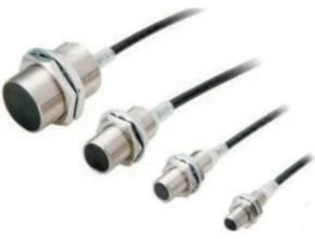
Omron E2ER/E2ERZ Proximity Sensors use high-frequency oscillation. They resist heat, chemicals, and water better than Rectangular Sensors. They are available in both shielded and unshielded models.
Proximity Sensors are available in models using high-frequency oscillation to detect ferrous and non-ferrous metal objects and in capacitive models to detect non-metal objects. Models are available with environment resistance, heat resistance, resistance to chemicals, and resistance to water.
Omron E2ER/E2ERZ Proximity Sensors Features and Benefits
- Fluororesin cable that withstands cutting
- A sealing method that eliminates gaps at cable joints and the resin filling work together to block ingress of cutting
- IP67G * degree of protection (JIS C 0920 Annex 1).
Ratings and Specifications
| Size Shielded Item Model | M8 | M12 | M18 | M30 | |
| Shielded | |||||
| E2ER-X2D@ | E2ER-X3D@ | E2ER-X7D@ | E2ER-X10D@ | ||
| Sensing distance | 2 mm ±10% | 3 mm ±10% | 7 mm ±10% | 10 mm ±10% | |
| Set distance *1 | 0 to 1.6 mm | 0 to 2.4 mm | 0 to 5.6 mm | 0 to 8 mm | |
| Differential travel | 15% max. of sensing distance | 10% max. of sensing distance | |||
| Detectable object | Ferrous metal (The sensing distance decreases with non-ferrous metal. Refer to Engineering Data on page 19.) | ||||
| Standard sensing object | Iron, 8 ´ 8 ´ 1 mm | Iron, 12 ´ 12 ´ 1 mm | Iron, 18 ´ 18 ´ 1 mm | Iron, 30 ´ 30 ´ 1 mm | |
| Response frequency *2 | 1.5 kHz | 1 kHz | 0.5 kHz | 0.4 kHz | |
| Power supply voltage | 10 to 30 VDC, (including 10% ripple (p-p)) | ||||
| Leakage current | 0.8 mA max. | ||||
| Control output | Load current | 3 to 100 mA | |||
| Residual voltage | 3 V max. (Load current: 100 mA, Cable length: 2 m) | ||||
| Indicators | D1 Models: Operation indicator (red), Setting indicator (green) D2 Models: Operation indicator (red) | ||||
| Operation mode (with sensing object approaching) | D1 Models: NO Refer to the timing charts under I/O Circuit Diagrams on page 21 for details. D2 Models: NC | ||||
| Protection circuits | Surge suppressor, Load short-circuit protection | ||||
| Ambient temperature range | Operating: -25 to 70°C, Storage: -40 to 85°C (with no icing or condensation) | ||||
| Ambient humidity range | Operating and Storage: 35% to 95% (with no condensation) | ||||
| Temperature influence | ±15% max. of sensing distance at 23°C in the temperature range of -25 to 70°C | ±10% max. of sensing distance at 23°C in the temperature range of -25 to 70°C | |||
| Voltage influence | ±1% max. of sensing distance at rated voltage in the rated voltage ±15% range | ||||
| Insulation resistance | 50 MÙ min. (at 500 VDC) between current-carrying parts and case | ||||
| Dielectric strength | 1,000 VAC, 50/60 Hz for 1 minute between current-carrying parts and case | ||||
| Vibration resistance (destruction) | 10 to 55 Hz, 1.5-mm double amplitude for 2 hours each in X, Y, and Z directions | ||||
| Shock resistance (destruction) | 500 m/s2 10 times each in X, Y, and Z directions | 1,000 m/s2 10 times each in X, Y, and Z directions | |||
| Degree of protection | IP67 (IEC 60529) and IP67G *3 (JIS C 0920 Annex 1) Passed OMRON’s Oil-resistant Component Evaluation Standards *4 (Cutting oil type: specified in JIS K 2241:2000, Temperature: 35 °C max.) | ||||
| Connection method | Pre-wired Models (Standard cable length: 2 m) and Pre-wired Connector Models (Standard cable length: 300 mm) | ||||
| Weight (packed state) | Pre-wired Models | Approx. 65 g | Approx. 75 g | Approx. 145 g | Approx. 215 g |
| Pre-wired Connector Models | Approx. 30 g | Approx. 40 g | Approx. 90 g | Approx. 155 g | |
|
Materi- als | Case | Stainless steel (SUS303) | Nickel-plated brass | ||
| Sensing surface | Polybutylene terephthalate (PBT) | ||||
| Clamping nuts | Nickel-plated brass | ||||
| Toothed washer | Zinc-plated iron | ||||
| Accessories | Instruction manual | ||||
- Use the Sensor within the range in which the setting indicator (green LED) is ON (except D2 Models).
- The response frequency is an average value.
- Measurement conditions are as follows: standard sensing object, a distance of twice the standard sensing object, and a set distance of half the sensing distance.
- The IP67G is the degree of protection which is defined according to the JIS (Japanese Industrial Standards).
- The IP67 indicates the same level of protection as defined by the IEC, and the G indicates that a device has resistance to oil.
- The Oil-resistant Component Evaluation Standards are OMRON’s own durability evaluation standards.
The Pre-wired Connector Model meets the degree of protection when it is correctly connected with an XS5@R Oil-resistant Connector. The degree of protection is not satisfied with the part where there is no XS5FR Oil-resistant Connector connected and cable wires are uncovered. And as for the Pre-wired Models, the degree of protection is not satisfied with the part where cable wires are uncovered.
Download Catalog: Environment-resistant Series
Ref: Omron.co.id
Read more articles :
Read more articles :
- Alcoaero Thermocouple
- Bi-metal pointer thermometer
- Trafag – Sensors and Controls
- Skon digital pressure gauges
- Dropsa Ultrasensor 2 Proximity and microswitch systems
- Pressure Switch 132 P Series
- MarelliMotori Series Motors Marine A_M – B_M
- Gastec WPT-132 Waste Water Test Kit
- Trafag TFS Float Level Switch
- MarelliMotori Series Generators Oil & Gas MJV – MJHV