
General
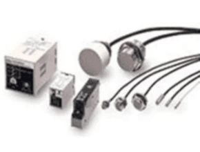
Omron E2C/E2C-H Separate Amplifier Compact design with smaller Sensor Head. Heat-resistance model available for application between ?10 and 200°C.
Feature
- Compact design with smaller Sensor Head.
- Heat-resistance model was available for application between ?10 and 200°C.
Omron E2C/E2C-H Separate Amplifier Lineup
Measurement conditions are as follows: standard sensing object, a distance of twice the standard sensing object, and a set distance of half the sensing distance.
*2. Refer to 6 for cable lengths when combining Amplifier Units and Sensors. The characteristic impedance of the high-frequency coaxial cable is 50 Ù.
Standard Models
| Sensor | Amplifier Units | ||||||
| Appearance | Stable | Model | Model | Power supply/ | Timer | Self- | |
| sensing | Output | function | diagnostic | ||||
| area *1 | output | ||||||
| 3,5 dia | 0.8 (1.8) mm | E2C-CR8A 3M | E2C-GE4A | DC/(NPN) | — | — | |
| E2C-GF4A | DC/(PNP) | — | — | ||||
| E2C-JC4AP 2M *2 | DC/(NPN) | Yes | Yes | ||||
| E2C-JC4A 2M | DC/(NPN) | Yes | — | ||||
| E2C-AM4A | DC/(NPN, PNP) | — | — | ||||
| E2C-AK4A | AC | — | — | ||||
| 3,5 dia | 0.8 (1.8) mm | E2C-CR8B 3M | E2C-GE4A | DC/(NPN) | — | — | |
| E2C-GF4A | DC/(PNP) | — | — | ||||
| E2C-JC4AP 2M *2 | DC/(NPN) | Yes | Yes | ||||
| E2C-JC4A 2M | DC/(NPN) | Yes | — | ||||
| E2C-AM4A | DC/(NPN, PNP) | — | — | ||||
| E2C-AK4A | AC | — | — | ||||
| M5 | 1 (2) mm | E2C-X1A 3M | E2C-GE4A | DC/(NPN) | — | — | |
| E2C-GF4A | DC/(PNP) | — | — | ||||
| E2C-JC4AP 2M *2 | DC/(NPN) | Yes | Yes | ||||
| E2C-JC4A 2M | DC/(NPN) | Yes | — | ||||
| E2C-AM4A | DC/(NPN, PNP) | — | — | ||||
| E2C-AK4A | AC | — | — | ||||
| 5,4 dia | 1 (2) mm | E2C-C1A 3M | E2C-GE4A | DC/(NPN) | — | — | |
| E2C-GF4A | DC/(PNP) | — | — | ||||
| E2C-JC4AP 2M *2 | DC/(NPN) | Yes | Yes | ||||
| E2C-JC4A 2M | DC/(NPN) | Yes | — | ||||
| E2C-AM4A | DC/(NPN, PNP) | — | — | ||||
| E2C-AK4A | AC | — | — | ||||
| M8 | 1.5 (3) mm | E2C-X1R5A 3M | E2C-GE4A | DC/(NPN) | — | — | |
| E2C-GF4A | DC/(PNP) | — | — | ||||
| E2C-JC4AP 2M *2 | DC/(NPN) | Yes | Yes | ||||
| E2C-JC4A 2M | DC/(NPN) | Yes | — | ||||
| E2C-AM4A | DC/(NPN, PNP) | — | — | ||||
| E2C-AK4A | AC | — | — | ||||
| M12 | 2 (5) mm | E2C-X2A 3M | E2C-JC4AP 2M *2 | DC/(NPN) | Yes | Yes | |
| E2C-JC4A 2M | DC/(NPN) | Yes | — | ||||
| E2C-AM4A | DC/(NPN, PNP) | — | — | ||||
| E2C-AK4A | AC | — | — | ||||
| M18 | 5 (10) mm | E2C-X5A 3M | E2C-AM4A | DC/(NPN, PNP) | — | — | |
| E2C-AK4A | AC | — | — | ||||
| M30 | 10 (18) mm | E2C-X10A 3M | E2C-AM4A | DC/(NPN, PNP) | — | — | |
| E2C-AK4A | AC | — | — | ||||
| 40 | 20 (50) mm | E2C-C20MA 3M | E2C-AM4A | DC/(NPN, PNP) | — | — | |
| dia. | E2C-AK4A | AC | — | — | |||
Note: characteristics will change if the cable length changes. Do not cut or extend the cable.
Accessories (Order Separately)
Mounting Brackets
A Mounting Bracket is not provided with the Sensor. Order a Mounting Bracket separately if required.
| Name | Model | Applicable Sensors | Remarks |
| Mounting Brackets | Y92E-F3R5 | E2C-CR8A, for 3.5 dia. | — |
| Y92E-F5R4 | E2C-C1A, for 5.4 dia. |
Connection Sockets
A Socket is not provided with the Amplifier Unit. Order a Socket separately if required
| Name | Model | Applicable Amplifier Unit | Remarks |
| Front Connection Sockets | PYFZ-08 | E2C-GE4A | Hold-down Clips (Order Separately) |
| E2C-GF4A | PYC-A1 | ||
| Sold as a set. | |||
| P2CF-08 | E2C-AM4A | — | |
| P2CF-11 | E2C-AK4A | ||
| Back Connection Sockets | P3G-08 | E2C-AM4A | |
| P3GA-11 | E2C-AK4A | ||
| PY08 | E2C-GE4A | ||
| E2C-GF4A |
Adapters
An Adapter is not provided with the Amplifier Unit. Order an Adapter separately if required
| Name | Model | Applicable Amplifier Unit | Remarks |
| Embedded Adapters | Y92F-30 | E2C-AM4A/-AK4A | — |
| Y92F-70 | |||
| Y92F-71 |
Omron E2C/E2C-H Separate Amplifier Specifications
Standard Models
Sensors
| Model | E2C-CR8A/ | E2C-X1A/ | E2C-X1R5A | E2C-X2A | E2C-X5A | E2C-X10A | E2C-C20MA | |
| -CR8B | -C1A | |||||||
| Sensing distance | 1.8 mm | 2 mm | 3 mm | 5 mm | 10 mm | 18 mm | 50 mm | |
| (at 23°C) | ||||||||
| Stable | Ambient | 0 to 0.8 mm | 0 to 1 mm | 0 to 1.5 mm | 0 to 2 mm | 0 to 5 mm | 0 to 10 mm | 0 to 20 mm |
| sensing | temperature | |||||||
| area | At 0 to 40°C | 0 to 1.2 mm | 0 to 1.5 mm | 0 to 2 mm | 0 to 2.5 mm | 0 to 7 mm | 0 to 15 mm | 0 to 28 mm |
| Differential travel | Refer to the amplifier unit specifications below. | |||||||
| Detectable object | Ferrous metal (The sensing distance decreases with non-ferrous metal. Refer to Data Sheet.) | |||||||
| Standard sensing object | Iron, 5 × 5 × 1 mm | Iron, 8 × | Iron, 12 × | Iron, 18 × | Iron, 30 × | Iron, 50 × | ||
| 8 × 1 mm | 12 × 1 mm | 18 × 1 mm | 30 × 1 mm | 50 × 1 mm | ||||
| Response | 1 kHz | 800 Hz | 350 Hz | 100 Hz | 50 Hz | |||
| frequency *1 | ||||||||
| Ambient | Operating/Storage: -25 to 70°C (with no icing or condensation) | |||||||
| temperature range | ||||||||
| Ambient | Operating/Storage: 35% to 95% (with no condensation) | |||||||
| humidity range | ||||||||
| Temperature | 15% max. of sensing distance at 23°C in the temperature range of -25 to 70°C | |||||||
| influence | ||||||||
| Vibration resistance | Destruction: 10 to 55 Hz, 1.5-mm double amplitude for 2 hours each in X and Y directions | |||||||
| Shock resistance | Destruction: 500 m/s2 3 times each in X and Y directions | |||||||
| Degree of protection | IEC 60529 IP67, in-house standards: oil-resistant | |||||||
| Connection method *2 | Pre-wired Models | |||||||
| High-frequency coaxial cable (Standard cable length: 3 m) | ||||||||
| Weight | Approx. 40 g | Approx. 45 g | Approx. 50 g | Approx. 60 g | Approx. 140 g | Approx. 270 g | Approx. 300 g | |
| (packed state) | ||||||||
| Materials | Case | Stainless steel | Brass | |||||
| Sensing | ABS resin | |||||||
| surface | ||||||||
| Cable | Vinyl chloride (PVC) | Polyethylene (PE) | ||||||
| Clamping | — | Brass, nickel-plated (except E2C-C1A) | ||||||
| nut | ||||||||
| Toothed | — | Iron, zinc-plated (except E2C-C1A) | ||||||
| washer | ||||||||
| Accessories | — | |||||||
*1. The minimum value when using the solid-state control output on the Amplifier Unit.
Measurement conditions are as follows: standard sensing object, a distance of twice the standard sensing object, and a set distance of half the sensing distance.
*2. Refer to 6 for cable lengths when combining Amplifier Units and Sensors. The ch. characteristic impedance of the high-frequency coaxial cable is 50 ?.
*1. The minimum value when using the solid-state control output on the Amplifier Unit.
Download Catalog: Separate Amplifier Proximity Sensor with Adjustment Potentiometer E2C or E2C-H
Ref: Omron.com
Other Article:
- Kem Kuppers Pickups and Amplifiers
- Omron E2EY Alumunium Detecting Proximity Sensor
- ECO Pulse Amplifiers Kem Kuppers Modular Pulse Amplifiers
- E2E-X DC 2-Wire Model Omron Standard Proximity Sensor
- E2E-X AC 2-Wire Model Omron Standard Proximity Sensor
- Proximity Sensor – RECHNER KA 0642
- INFW 020 GSP
- Neodyn 105P/105PP Series Miniature Tamper Proof Pressure Switch
- Technoton GNOM DP Axle Load Sensor
- Berthold Technologies – Measurement Solutions from the experts