
Overview
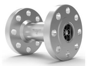
The HM F turbine flow meter series (F for flange connections) is used to measure continuous and discontinuous flow rates. They are mainly used for lubrication and non-lubrication media. They are particularly suitable for low and medium viscosity liquids, such as water, emulsions, glycol mixtures and light oils. Only high-grade steels that even withstand corrosive liquids are used in the production of turbine flow meters. Combined with the use of tungsten carbide bearings, the HM F guarantees optimum measurement accuracy and an extremely long service life even under the toughest application conditions.
The combination of various turbine wheel dimensions and blade geometries allows a wide range of sizes that can cover a huge measuring range. This makes the HM F ideal for a variety of applications in the field of metering as well as for monitoring, mixing and dosing. Short response times, very dynamic performance and high measurement accuracy ensure accurate regulation and control of flow rates in the most demanding applications.
For applications in hazardous areas, we offer intrinsically safe sensors and amplifiers with Ex protection in accordance with ATEX, IECEx, CSA and other standards. Additional certifications such as EAC (TR-CU) are available.
Principle and Design
Turbine flow meters (HM) are volume counters operating on the Woltmann impeller counter principle. They record the flow rate in the flow-through in a pipe via the average flow velocity. The flow of the medium is directed at the turbine wheel in the axial direction and so rotated. The speed of the freely turning wheel over a wide range is
directly proportional to the average flow velocity. The low weight of the turbine wheel ensures very short response times as well as very dynamic behaviour in flow changes. Two flow straighteners generate quasi-laminar flow, which in turn contributes to increasing the measurement accuracy.
The speed of the turbine wheel is tapped by the contactless sensor technology (transducer) through the housing wall. The sensor system can be variably adapted to meet the requirements of the respective application. This also allows, for example, providing a signal to indicate the direction of flow.
Pulses per unit of volume are available for analysis. The calibration factor (K-factor) of the flow meter describes the exact pulse rate per unit of volume. In order to determine the individual calibration factor of a flow meter, we calibrate each of our meters in house prior to delivery. The operating viscosity specified by the customer is taken into account for calibration. A corresponding calibration certificate is included with every flow meter we supply.
The KEM turbines feature a short response time between 5 and 50 ms depending on the nominal width, which is advantageous for precise filling processes. Turbine flow meters have a resolution of up to 100,000 pulses per litre. The milled and turned precision components are the reason why the HM series has neither wetted weld seams nor soldered connections. All market-related requirements for piping and material standards can thus be fully guaranteed.
Features
- High measuring accuracy up to ±0.1 %1)
- Exceptional repeatability of ±0.05 %
- Short response times (from 5 ms)
- Robust carbide bearing
- Medium temperature: -60 °C up to +350 °C [-76 °F up to +662 °F]
- Different nominal sizes
- Pressure stage up to PN400/6000 PSI
- Flange standard DIN Form B, ASME Raised Face (RF) & Ring Type Joint (RTJ)
Technical Data – General
- Measuring Accuracy ±0.1 %5)
- Repeatability ±0.05 % (under the same conditions)
- Linearity ±1 % of actual flow
- Measuring Span
- Standard: 1:10
- Extended: on request
- Viscosity Range 0.8 up to 30 mm2/s
- Materials
- Housing: as per DIN 1.4404 [AISI 316L], other material on request
- Wheels: as per DIN 1.4460 [AISI 329], other material on request
- Bearing: Tungsten carbide sleeve bearing
- Medium Temperature -60 °C up to +350 °C [-76 °F up to +662 °F]
- Dimensions See dimensional drawing
Applications
- Consumption measurement
- Filling process
- Dosing systems
- 2-component mixing plants
- Test stands
- Water (polluted and demineralized)
- Hydraulic and gear oils
- Fuels, gasoline, kerosene
- Coolants
- Additives
- Solvents
- Pharmaceutical liquids
- Cryogenic fluids
Specifications
Technical Data
- Measuring Ranges: 0.3 up to 13,400 l/min
- Measuring Accuracy: up to ±0.1 %
- Repeatability: ±0.05 % (under the same conditions)
- Linearity: ±1 % of actual flow
- Measuring Span:
- Standard: 1:10
- Extended: on request
- Viscosity Range: 0.8 up to 30 mm²/s
- Materials:
- Housing: as per DIN 1.4404 [AISI 316L] (others on request)
- Wheels: as per DIN 1.4460 [AISI 329] (others on request)
- Bearing: Tungsten carbide sleeve bearing
- Pressure: up to 400 bar [5,800 psi]
- Medium Temperature: -60 °C up to +350 °C [-76 °F up to +662 °F]
Calibration
- In-house calibration is performed on volumetric calibration rigs or at the wishes of the customer in our DAkkS calibration laboratory.
- The KEM calibration lab uses a high-precision load cell system. With an accuracy of 0.05 % for the mass and 0.1 % for the volume of flowing liquids, we occupy a leading position worldwide. The German Accreditation Body (DAkkS) has accredited the laboratory with engineers, processes and measuring equipment in accordance with the international standard DIN EN ISO/IEC 17025:2018.
- The KEM calibration certificate not only verifies the accuracy of a flow meter, but also guarantees its traceability to national standards as well as ensuring all requirements according to international quality standards are met.
- The calibrations are performed with different hydrocarbons. This ensures the optimum simulation of changing operating conditions in density and viscosity even when temperatures change. This way the primary viscosity for the use of the flow meter can be specifically taken into account when viscosity fluctuations occur in a customized application.
- The calibration result is the specified calibration factor (K-factor) in pulses per liter. This K-factor accordingly applies only at a certain flow velocity or a certain flow rate.
- The calibration factor varies only very slightly at different volume flow rates. The individual measuring points provide the calibration curve of the flow meter from which the average K-factor is determined. The average calibration factor applies to the entire measuring range.
- The linearity error specification (percentage deviation) refers to the average K-factor. To further increase the measurement accuracy in onsite use, specific K-factors can be used to calculate the flow rate. For this, KEM also supplies optional special electronics.
Download Datasheet: HM F Series Kem Kuppers Turbine Flow Meter
Reference: www.kem-kueppers.com
Other Articles :
- Kem Kuppers ECO Pulse Amplifiers
- GFM Mass Flow Meters
- Kem Kuppers HM R Turbine Flow Meter
- Kem Kuppers Evaluation Electronics and Additional Accessories
- Dwyer GFM Series Gas Mass Flow Meter & Controllers
- HM P Series Kem Kuppers Turbine Flow Meters
- HM TRI Series Kem Kuppers Turbine Flow Meters
- HM AC Series Kem Kuppers Turbine Flow Meters
- HM TC-NS Series Kem Kuppers Turbine Flow Meters
- HM TC-R Series Kem Kuppers Turbine Flow Meters