
4WS(E)2EM 6-2X/…
Valves of this type are electrically operated, 2-stage directional servo valves with porting patterns according to ISO 4401-03-02-0-05. They are mainly used to control position, force, pressure, or velocity.
These valves are made of an electro-mechanical converter (torque motor) (1), a hydraulic amplifier (principle: nozzle flapper plate) (2), and a control spool (3) in a sleeve (2nd stage) which is connected with the torque motor via mechanical feedback.
An electrical input signal at the coils (4) of the torque motor generates a force by means of a permanent magnet which acts on the armature (5), and in connection with a torque tube (6) results in a torque. This causes the flapper plate (7) which is connected to the torque tube (6) via a bolt to move from the central position between the two control nozzles (8), and a pressure differential is created across the front sides of the control spool (3).
The pressure differential results in the spool changing its position, which results in the pressure port being connected to one actuator port and, at the same time, the other actuator port being connected to the return flow port.
The control spool is connected to the flapper plate or the torque motor by means of a bending spring (mechanical feedback) (9). The position of the spool is changed until the feedback torque across the bending spring and the electro-magnetic torque of the torque motor are balanced and the pressure differential at the nozzle flapper plate system becomes zero.
The stroke of the control spool and consequently the flow of the servo valve are controlled proportional to the electrical input signal. It must be noted that the flow depends on the valve pressure drop.
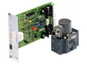
Type 4WS2EM 6-2X/… for external control electronics
External control electronics (servo amplifier) serve the actuation of the valve, amplifying an analog input signal (command value) so that with the output signal, the servo valve is actuated in a flow-controlled form.
Type 4WSE2EM 6-2X/… with OBE
For amplification of the analog input signal, special control electronics (10) adjusted to this valve type have been integrated. They are attached to the connector (11) in the cover cap of the torque motor.
Feature
- Valve to control position, force, pressure, or velocity
- 2-stage servo valve with mechanical feedback
- 1st stage nozzle/flapper plate amplifier
- For subplate mounting: Porting pattern according to ISO 4401
- Dry control motor, no contamination of the solenoid gaps by the hydraulic fluid
- Can also be used as a 3-way version
- Wear-free control spool return element
- Valve and integrated control electronics are adjusted and tested
- Pressure chambers at the control sleeve with gap seal, therefore no wear of the seal ring
- Filter for 1st stage freely accessible from the outside
Specification
| GENERAL | |||
| Type | 4WS(E)2EM | ||
| Size | 6 | ||
| Component series | 2X | ||
| Porting pattern | ISO 4401-03-02-0-05 | ||
| Installation position | any – ensure that during the start-up of the system, the pilot control is supplied with sufficient pressure (?10 bar). | ||
| Storage temperature range | °C | -20 … +80 | |
| Weight | kg | 01.01 | |
| Ambient temperature range | with OBE | °C | -20 … +60 |
| without OBE | °C | -30 … +100 | |
Hydraulic
| Type | 4WS(E)2EM | ||
| Maximum operating pressure | bar | 315 | |
| Maximum operating pressure | Anschluss A | bar | 315 |
| Port B | bar | 315 | |
| Port P | bar | 315 | |
| Return flow pressure | Port T | bar | Pressure peaks < 100, static < 10 |
| Rated flows qv nom at 70 bar valve pressure differential (35 bar/control edge) 1) | l/min | 2 | |
| Maximum control spool stroke possible 2) | % | 120 … 170 | |
| Hydraulic fluid | see table | ||
| Hydraulic fluid temperature range | °C | -30 … +80 | |
| preferably | °C | +40 … +50 | |
| Maximum admissible degree of contamination of the hydraulic fluid, cleanliness class according to ISO 4406 (c) 3) | Class 18/16/13 according to ISO 4406 (c) | ||
| Viscosity range | mm²/s | 15 … 380 | |
| preferably | mm²/s | 30 … 45 | |
| Feedback system | mechanical | ||
| Hysteresis (dither-optimized) | % | ? 1.5 | |
| Range of inversion (dither-optimized) | % | ? 0.2 | |
| Response sensitivity (dither-optimized) | % | ? 0.2 | |
| Pressure amplification with 1 % control spool stroke change (from the hydraulic zero point) 4) | % | ? 50 | |
| Zero adjustment flow over the entire operating pressure range 5) | % | ? 3 | |
| Zero shift upon change of | Hydraulic fluid temperature | %/20° C | ? 1 |
| Ambient temperature | %/20° C | ? 1 | |
| Operating pressure 80 … 120 % of pP | %/100 bar | ? 2 | |
| Return flow pressure 0 … 10 % of pP | %/bar | ? 1 | |
1)Tolerance ±10 % with valve pressure differential p = 70 bar
2)With mechanical end position (in an error case) related to nominal stroke
3)The cleanliness classes specified for the components must be adhered to in hydraulic systems. Effective filtration prevents faults and simultaneously increases the life cycle of the components.
4)of pp from the hydraulic zero point
5)long-term ? 5%
Electrical
| Zero flow (with spool overlap “E”, measured without dither signal) | l/min | ||
| Hydraulic fluid | Classification | Suitable sealing materials | Standards |
| Mineral oils and related hydrocarbons | HL, HLP | NBR / FKM | DIN 51524 |
| For more information and data on the use of other hydraulic fluids please contact us. | |||
| Type | 4WS(E)2EM | ||
| Size | 6 | ||
| Protection class according to EN 60529 | IP65 (If a suitable and a correctly mounted mating connector are used.) | ||
| Type of signal | analog | ||
| Inductivity 1) | Serial connection | H | 1 |
| Parallel connection | H | 00.25 | |
1)With 60 Hz and 100% rated current
Download Datasheet: Rexroth 4WS.2E Directional servo-valves in 4-way variant
Another Article:
- Rotary Paddle Level Switch Parker JC7
- Parker JD-100 Diaphragm Level Switch Type for Powder
- GPE 31611 Capacitance Center Sensor
- Hengstler Position Indicator Tico 731 Position Display
- Tico 772 Hengstler Position Display