
Description
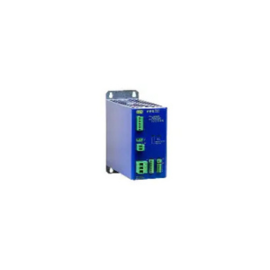
J Schneider AKKUTEC 2420 3ph, The battery buffered DC power supply of the series AKKUTEC is working according the stand-by parallel mode and ensures in connection with a lead-acid accumulator a safe continuous DC power supply in case of mains failure.
The power supply has the following features:
- Primary switched power supply with I/U-charging characteristics
- active power factor correction (PFC)
- Battery management by micro-controller
- Battery voltage tracking of the charging voltage by external sensor module (optional)
- Display- and control panel for mount in cabinet door or module (optional)
- redundant operation or Master-/Slave-operation possible
J Schneider AKKUTEC 2420 3ph Technical Data
| Nominal input voltage | 3 x 400 – 500 V AC -15% +10% |
| Nominal frequency | 45 – 65 Hz |
| System voltage | 24 V DC |
| Output voltage(depending on state of Charge of the battery) | |
| voltage range | |
| – with temperature tracking | 19,8 V DC – 27,8 V DC |
| – without temperature tracking | 19,8 V DC – 26,8 V DC |
| Nominal utput current | 20 A at 100% ED |
| Protective system | IP 20 |
| safe separation (safe separation between input and output) | acc. EN61558-2-17 |
| operational temperature | 0 – 40 °C |
| short circuit protection | electronic, short-circuit-proof output |
| Battery | external |
| Battery fuse | external |
| back-up time | depending on battery |
| charging characteristics | I/U DIN 41773 part 1 |
| Opt. | temperature tracking |
| boost Charge via control contact (up to 28,6V) | |
| final charging voltage | |
| without temp.- sensor | 26,8 V DC ± 0,4% |
| with temp.- sensor at 25° | 27,8 V DC ± 0,4% |
| charging current at 100% load | 2:00 AM |
| charging current at 0% load | 22 A |
| deep discharge protection | load rejection at battery voltage ? 19,8 V |
| LED-display | mains / battery operation ‘Netz OK’ LED green |
| General error ‘Fehler’ LED yellow | |
| battery voltage within LED green | |
| battery voltage above LED green | |
| Relays-outputs | mains/UPS-operation 0,5 A /30 V DC |
| General error 0,5 A /30 V DC | |
| voltage above 0,5 A /30 V DC | |
| voltage within 0,5 A /30 V DC | |
| control inputs referring to earth on +24VDC | Shut down |
| boost charge | |
| Special features | active current share at Master – Slave respectively redundant Operation with CS bus |
| time function (load rejection after adjustable back-up time) | |
| expandable | In 20 A steps Master/Slave |
| active PFC | harmonic ripple at input according to EN 61000-3-2 |
| PF ~ 0,99 | |
| Batterymanagement | Batterymanagement with internal micro controler, |
| battery circuit control | |
| control battery circuit/battery fuse each 60 sec. | |
| Real battery power measurement | battery load test during operation. (load of the battery with simultaneous voltage measurement) each 24h |
| EMI-regulations | EN 55011/ 1998 class A Group1 |
| EN 50082-1/1.92 | |
| EN 50178 | |
| type of construction | module |
| connection primary | with terminals |
| secondary Ua | 2,5 mm² |
| Secondary batt | 6 mm² |
| 4 mm² | |
| dimensions | 101 x 241 x 244 mm (B x H x T) |
| weight | 2,6 kg |
| Options | |
| control and Display panel | well readable, 20-digit, 2-line Alpha numeric LC-Display with back-ground illumination |
| separate possible adjustements for contrast and brightness | |
| supply and data Transfer with 2 wire bus, thus low wiring activity necessary | |
| reading and writing of charging and control parameters | |
| display of status messages in plain text | |
| acoustic Signal for warnings respectively Errors (deactivatable) | |
| possibility of Display of the operational data, for redundant systems also with only one Panel possible. | |
| easy user prompting | |
| 3-button operation | |
| protection of functions by Password Levels | |
| suitable for built in cabinet door (protective system IP54) | |
| Temperature tracking | with temperature sensor at terminal strip IO-1 and 2 the charging voltage is automatically adjusted to the environmental conditions (26,8-27,8 V). Overtemperature at the batteries (above 45°C) is displayed and announced. |
| Shut-down | Abort of the UPS – operation |
| potentialfree gate input | |
| Switch level: 24 V DC (6-45 V DC) | |
| Fixation | Mounting bracket for mounting plate |
| UL approvals | No |
Reference : j-schneider.de
Download : Datasheet
Other Article:
- J. Schneider AKKUTEC 2403 DC
- J. Schneider AKKUTEC 2403 K
- J. Schneider C-TEC 2440-4 P
- Kracht DT 5 Duo Tec Series – Gear Pump
- J. Schneider NBBH 2401
- J. Schneider C-TEC 1203
- J. Schneider C-TEC 1225 P
- J. Schneider C-TEC 2403 USB
- Kracht KP 1 Duo Tec – Gear Pump Series
- J. Schneider C-TEC 2403-1of
- J. Schneider C-TEC 4815 P
- J. Schneider AC C-TEC 2403-1-400